Control throws, Final assembly – E-flite Ultimate 3D Profile ARF User Manual
Page 30
31
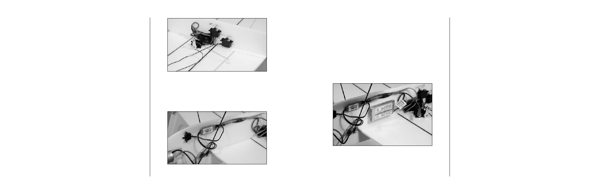
Note: You may need to change the
connectors on the speed control to match those
of the motor or battery. Also be careful of the
spinning propeller.
❍
3. Use the full piece of hook and loop material
to attach the battery to the fuselage. Read
through the section on Center of Gravity to
choose the correct location for the battery.
For best flight performance of the Ultimate, a
high center of gravity is important. To achieve
this, we recommend locating the battery on the
cabane strut even with the front edge.
Control Throws
Tribute
:
Low Rate
High Rate
Aileron:
1" (25mm) Up
1
1/4
" (32mm) Up
1" (25mm) Down
1
1/4
" (32mm) Down
Elevator:
1
1/4
" (32mm) Up
2
1/2
" (63mm) Up
1
1/4
" (32mm) Down 2
1/2
" (63mm) Down
Rudder:
3
1/8
" (79mm) Right
4
1/4
" (108mm) Left
3
1/8
" (79mm) Right
4
1/4
" (108mm) Left
Ultimate
:
Aileron:
1/2" (13mm) Up
7/8" (22mm) Up
1/2" (13mm) Down
7/8" (22mm) Down
Elevator:
1
1/4
" (32mm) Up
2
1/4
" (57mm) Up
1
1/4
" (32mm) Down 2
1/4
" (57mm) Down
Rudder:
2
1/8
" (54mm) Right
3
1 /8
" (79mm) Right
2
1/8
" (54mm) Left
3
1/8
" (79mm) Left
30
Final Assembly
Required Parts
Airframe
Servo tape
Hook and loop
Required Tools and Adhesives
Hobby knife
Foam-safe CA
Receiver
Motor battery
20 Amp speed control
❍
1. Cut a small hole in the fuselage to pass the
aileron servo lead through. Plug the servos
into the receiver. Cut a piece of hook and
loop material in half. Attach the receiver to
the fuselage using the cut piece of hook and
loop material. Route the antenna either down
the fuselage or under the wing.
❍
2. Attach the speed control to the fuselage using
the other half of the hook and loop material.
Set up the speed control using the instructions
provided with the speed control.