Transmitter and receiver binding - bnf, Stabilizer installation - bnf/pnp – E-flite Hawker Hurricane 25e PNP User Manual
Page 7
7
E-flite Hurricane 25e PNP/BNF Assembly Manual
EN
Transmitter and Receiver Binding - BNF
Required Parts
Fuselage assembly Transmitter
Bind plug
Binding is the process of programming the receiver
of the control unit to recognize the GUID (Globally
Unique Identifier) code of a single specific transmitter.
You need to ‘bind’ your chosen Spektrum
™
DSM2
™
/
DSMX
™
technology equipped aircraft transmitter to the
receiver for proper operation.
Note: Any JR
®
or Spektrum full range DSM2
™
/
DSMX
™
transmitter can bind to the Spektrum
AR600 receiver. Please visit www.bindnfly.com
for a complete list of compatible transmitters.
Note: When using a Futaba transmitter with a
Spektrum DSM module, you must reverse the
throttle channel.
BINDING PROCEDURE
BIND PLUG
1. Read transmitter instructions for binding to a
receiver (location of transmitter’s Bind control).
2. Make sure transmitter is powered off.
3. Move the transmitter controls to neutral (flight
controls: rudder, elevators and ailerons) or to low
positions (throttle, throttle trim, and flight control
trims).*
4. Install a bind plug in the receiver’s bind port.
5. Connect the flight battery to the ESC.
6. Power on the ESC switch. The receiver LED will
begin to flash rapidly under the rear hatch.
7. Power on the transmitter while holding the
transmitter bind button or switch. Refer to
your transmitter’s manual for binding button
or switch instructions.
8. When the receiver binds to the transmitter, the
light on the receiver will be solid and the ESC will
produce a series of sounds. The series of sounds is a
long tone, then 3 short tones that confirm the LVC is
set for the ESC.
9. Remove the bind plug from the bind port in
the receiver.
10. Safely store the bind plug (some owners attach
the bind plug to their transmitter using two-part
loops and clips).
11. The receiver should keep the binding to the
transmitter until another binding is done.
* The throttle will not arm if the transmitter’s
throttle control is not put at the lowest position.
If you encounter problems, obey binding instructions
and refer to transmitter troubleshooting guide for other
instructions. If needed, contact the appropriate Horizon
Product Support office.
Stabilizer Installation - BNF/PNP
Required Parts
Fuselage assembly Stabilizer assembly
Required Tools and Adhesives
30-minute epoxy
Mixing stick
Mixing cup
Epoxy brush
Petroleum jelly
Paper towel
Denatured alcohol
Before installing the stabilizer, we highly recommend
test fitting all parts before mixing epoxy. If the epoxy
begins to cure before parts are assembled, it will be
difficult to re-use items where epoxy has been applied.
When installing the stabilizer, make sure to glue
tube ONLY to the stabilizer. This will allow easy
removal of the tube if the stabilizer becomes
damaged and requires replacement.
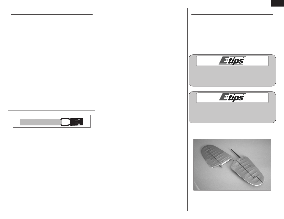
1. Separate the stabilizer halves, leaving the tube in
one of the stabilizer halves.