Series 994 installation instructions, Parallel indoors above ground, Installation – Watts 994 User Manual
Page 3: Start up
3
Series 994 Installation Instructions
*For additional information on Watts insulated enclosures refer to literature ES-WB.
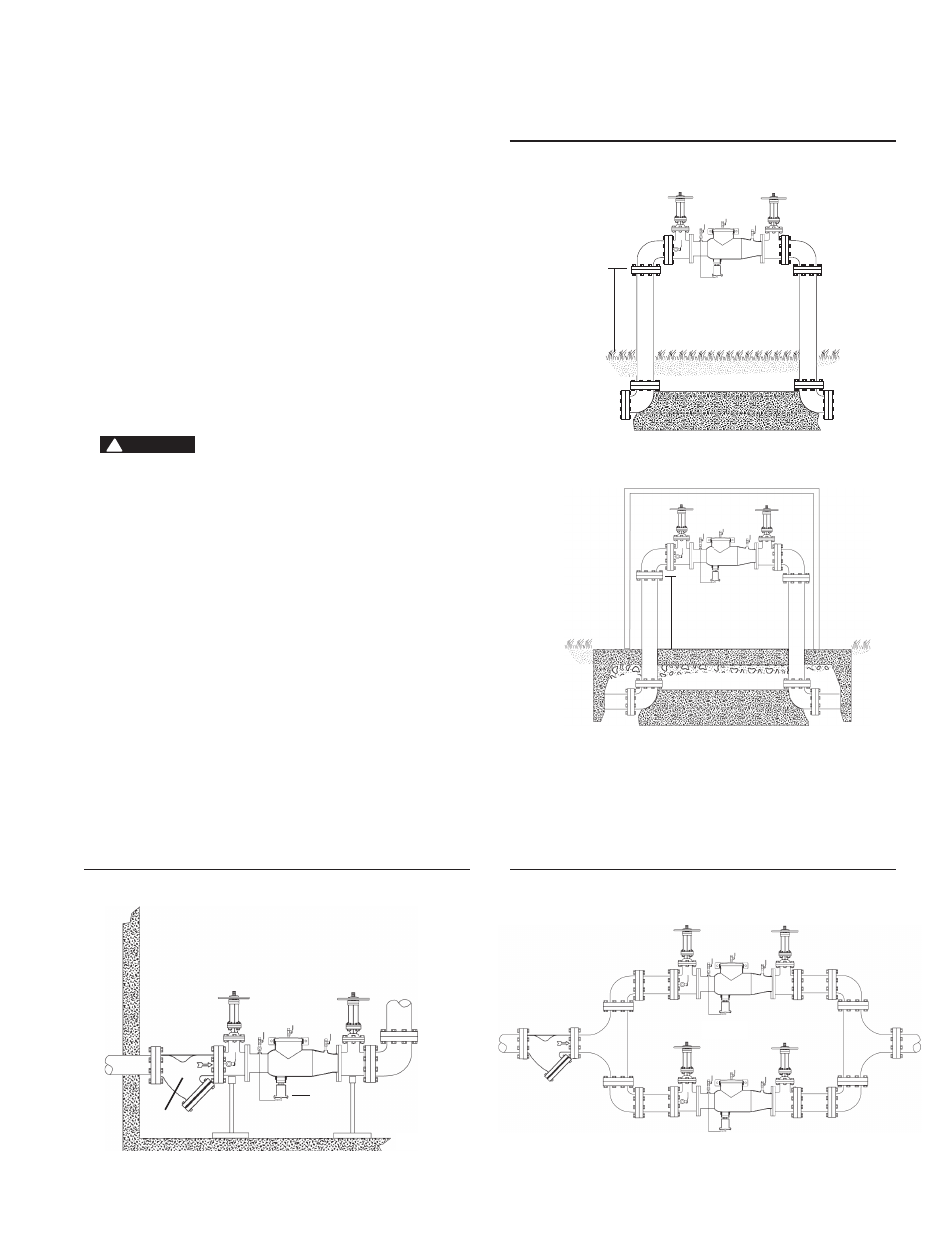
Parallel
Indoors
Above Ground
12” (300mm) min.
Refer to
Local Codes
Strainer
12” (300mm) min.
Refer to
Local Codes
12” (300mm) min.
Refer to Local Codes
*Insulated Enclosure
Installation
A. Series 994 shall be installed in a horizontal po si tion. The shutoff
valve with the test cock is to be mounted on the inlet side of the
back flow pre ven ter. The test cock is on the in let side of the shut-
off valve.
B. The 994 should always be installed in an ac ces si ble lo ca tion to
fa cil i tate test ing and ser vic ing. Check the state and local codes
to en sure that the back flow pre ven ter is installed in com pli ance,
such as the prop er height above the ground. The back flow pre-
venter must be sup port ed and is not de signed to car ry full weight
of the stand pipe.
C. Water discharge from the relief valve should be vented in ac cor-
dance with code re quire ments. The relief valve should never be
sol id ly piped into a drain age ditch, sew er or sump. The dis charge
should be funneled through a Watts air gap fitting piped to a floor
drain.
D. Watts recommends a strainer be in stalled ahead of Watts Series
994 as sem blies to pro tect the discs from un nec es sary foul ing.
CAUTION
!
Do not install a strainer ahead of the backflow pre ven ter on
seldom-used, emergency water lines (i.e. fire sprinkler lines). The
strainer mesh could potentially become clogged with debris pres-
ent in the water and cause water blockage during an emer gen cy.
Start Up
E. The downstream shutoff should be closed. Open up stream slow-
ly, fill the valve and bleed the air through Test cock 2, 3 and 4.
When valve is filled, open the down stream shutoff slowly and fill
the wa ter sup ply sys tem. This is nec es sary to avoid wa ter ham-
mer or shock dam age.
F. The installation of a Watts air gap with the drain line ter mi nat ing
above a floor drain will handle any normal dis charge or nuisance
spit ting through the relief valve. How ev er, floor drain size may
need to be de signed to pre vent water damage caused by a cat a-
stroph ic fail ure con di tion. Do not reduce the size of the drain line
from the air gap fit ting.
G. Two or more smaller size valves can be piped in parallel (when
ap proved) to serve a large supply pipe main. This type of in stal la-
tion is employed where in crease capacity is needed be yond that
pro vid ed by a single valve and per mits test ing or ser vic ing of an
in di vid u al valve with out shut ting down the com plete line.
The number of assemblies used in par al lel should be de ter mined
by the en gi neer’s judge ment based on the op er at ing conditions
of a spe cif ic in stal la tion.
994
994
994