Basic installation instructions, Series 994 reduced pressure zone assemblies, Location and installation considerations – Watts 994 User Manual
Page 2
2
Location and Installation Considerations
1. Backflow preventers must be installed in high-visibility lo ca tions in
order to allow for immediate notice of telltale discharge or oth er
mal func tion. This location should also facilitate testing and ser vic-
ing and protect against freezing and vandalism.
2.
Installation procedures must comply with all state and lo cal
codes.
3. Installing a backflow preventer in a pit or vault is not rec om mend-
ed. An air gap be low the relief port must be maintained so as to
avoid flood ing and sub mer sion of the assembly, which may lead
to a cross-connection. Watts recommends installations in doors
or above ground in an in su lat ed enclosure. (Refer to literature
ES-WB)
4. A strainer should be installed ahead of the backflow pre ven ter to
protect the discs from unnecessary fouling.
CAUTION
!
Do not install a strainer ahead of the backflow pre ven ter on
seldom-used, emergency water lines (i.e. fire sprinkler lines). The
strainer mesh could potentially become clogged with debris pres-
ent in the water and cause water blockage during an emer gen cy.
5. Normal discharge and nuisance spitting are ac com mo dat ed by
the use of a Watts air gap fitting and a fabricated indirect waste
line. Floor drains of the same size
MUST be provided in case of
ex ces sive discharge.
6. When a Series 994 backflow preventer is installed for dead-end
ser vice applications, dis charge from the relief vent may occur
due to wa ter supply pressure fluc tu a tion during static no-flow
con di tions. A check valve may be re quired ahead of the backflow
preventer.
7.
ASSEMBLY: If the backflow preventer is disassembled dur ing
in stal la tion, it
MUST be reassembled in its proper order. The gate
valve with the test cock is to mounted on the inlet side of the
back flow pre ven ter. The test cock must be on the inlet side of the
wedge. Failure to reassemble correctly will result in possible wa ter
damage due to excessive discharge from the relief port/vent and
possible mal func tion of the backflow preventer.
8. Prior to installation, thoroughly flush pipe line to re move any for-
eign matter.
9.
START UP at Initial Installations and After Servicing: The down-
stream shutoff should be closed. Slowly open upstream shutoff
and allow the backflow preventer to fill slowly. Bleed air at each
test cock. When backflow preventer is filled, slowly open the
down stream shut off and fill the water supply system. This is nec-
es sary to avoid water hammer or shock damage.
NOTICE
Assembly body should not be painted.
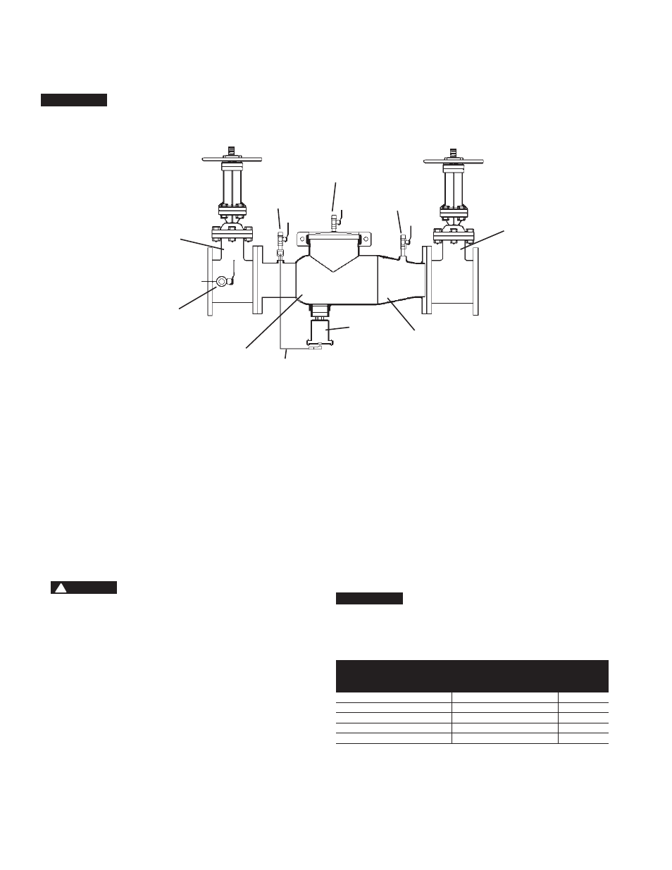
Figure 1
ValVE SizE
Typical FlOw RaTES aS
SizEd By FlOOR dRain
ManuFacTuRERS
dRain SizE
in.
mm
2
1
⁄
2
65
55 gpm
2
3
80
112 gpm
3
4
100
170 gpm
4
6, 8, 10
150, 200, 250
350 gpm
5
Basic Installation Instructions
Series 994 Reduced Pressure Zone Assemblies
#2 Test Cock
#3 Test Cock
#4 Test Cock
Outlet
Shutoff
#2 Check
Relief
Valve
Sensing
Line
1st Check
#1 Test Cock
Inlet Shutoff
Valve
NOTICE
The flange gasket bolts for the gate valves should be re tight ened during
in stal la tion as the bolts may have loos ened due to storage and ship ping.