Test no. 1 - test no. 1 check valve, Test no. 2 - test no. 2 check valve – Watts TK-DL User Manual
Page 4
4
The following Test Procedure is one of several that is recognized throughout the United States for verification of the functioning of
Backflow preventers.
The following procedure is not a specific recommendation. The Watts series of test kits are capable of performing any of the recog-
nized Backflow test procedures.
A. Flush all test cocks.
B. Turn tester on (before connecting hoses).
Tester must read all zeroes. Close VA and VB.
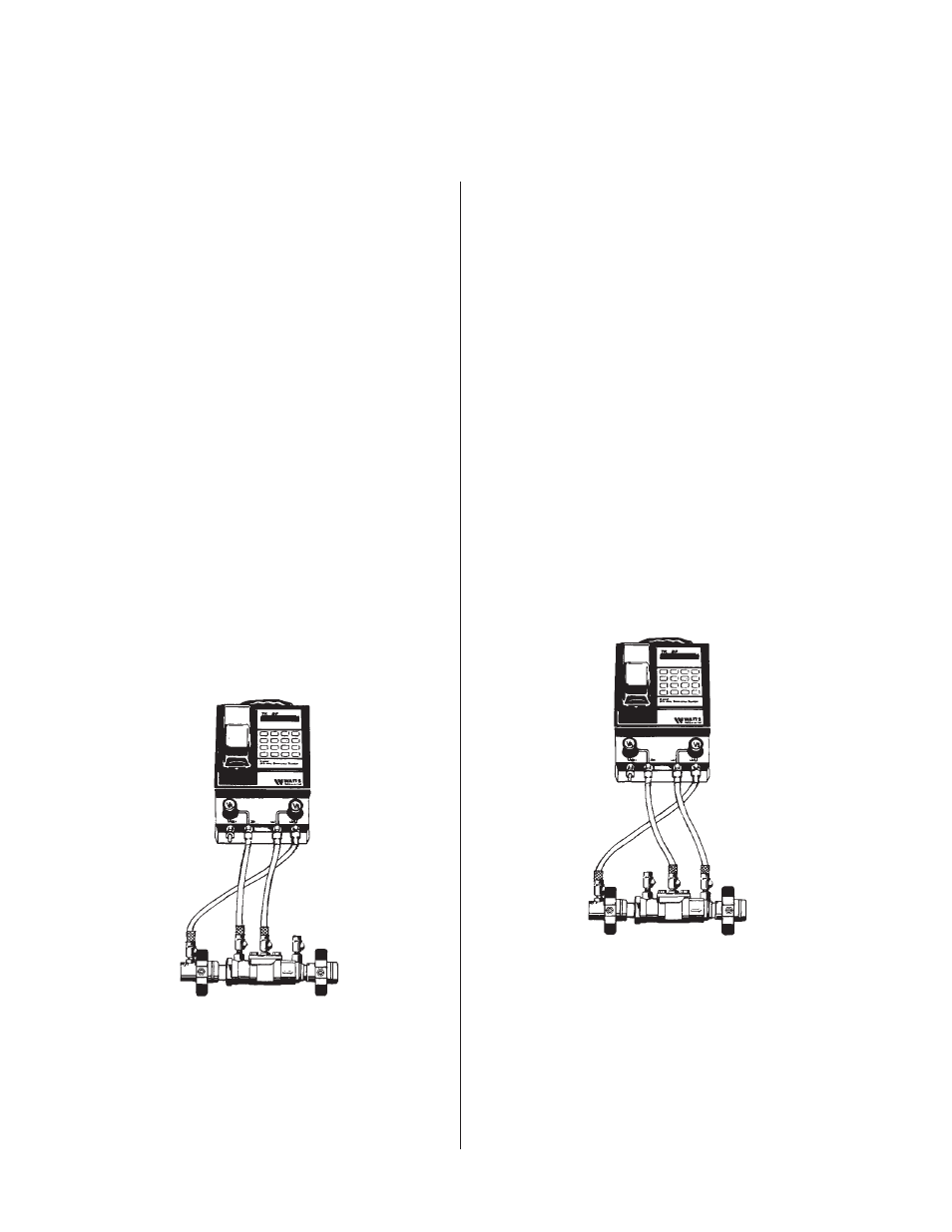
Test No. 1 - Test No. 1 Check Valve
1. Install high side hose between TC #2 and tester connection
A.
2. Install low side hose between TC #3 and tester connection B.
3. Open VA then TC #2, bleed hose, then close VA.
4. Open VB then TC #3, bleed hose, then close VB.
5. Install a bypass hose between VB and TC #1. Open TC #1
and bleed by loosening hose connection at VB. Tighten
hose connection, fully open VB.
Push - Print Head (wait) then Push - Start Test.
6. Close shutoff valve #2 then #1.
7. Slowly open VA and lower high side pressure about -2 PSID
below the low side pressure (differential reading about -2.0
PSID). Close VA. If reading is maintained, record as “tight”. If
reading returns to 0 and the pressure A increases to pressure
B, the check is recorded as leaking. If the reading returns to
+PSID, No. 2 shutoff valve is leaking excessively and must be
replaced to test the valve.
8. Close all test cocks, remove hoses from TC #2 and TC #3
and TC #1. reopen shutoff valve #1. Proceed to Test No. 2.
Push - Stop Test.
Test No. 2 - Test No. 2 Check Valve
1. Install high side hose between TC #3 and tester connection A.
2. Install low side hose between TC #4 and tester connection B.
3. Open VA then TC #3, bleed hose, then close VA.
4. Open VB then TC #4, bleed hose, then close VB.
5. Install a bypass hose between VB and TC #1.
Loosen hose at VB, open TC #1 and bleed, retighten hose
connection.
Push - Start Test.
6. Close shutoff valve #1.
7. Slowly open VA and lower high side pressure about -2 PSID
below the low side pressure (differential reading about -2.0
PSID). Close VA. If reading is maintained, record as “tight”. If
reading returns to 0 and the pressure A increases to
pressure B, the check is recorded as leaking. If the reading
returns to + PSID, No. 2 shutoff valve is leaking excessively
and must be replaced to test the valve.
Push - Stop Test.
V
H L
V
1
2
3
4
1
2
3
4
V
H L
V
Test Procedure for Double Check Valve Assembly (DC)