Test procedure for pressure vacuum breakers – Watts TK-DL User Manual
Page 2
2
The following Test Procedure is one of several that is recognized
throughout the United States for verification of the functioning of
Backflow preventers.
The following procedure is not a specific recommendation. The
Watts series of test kits are capable of performing any of the
recognized Backflow test procedures.
NOTICE
For both of the following tests, the TK-DL must be held at the
same level as the assembly being tested.
A. Flush TC #1 and #2.
B. Turn tester on (before connecting hose). Tester
must read all zeros. Close VA and VB.
Test No. 1 - Air Inlet
1. Install high side hose between TC #2 and tester connection
A.
2. Open VA then TC #2. Bleed hose, then close VA.
3. Close shutoff valve #2 then #1.
Push - Print Head (wait) then Push -
Start Test
4. Slowly open VA when air inlet float opens, push “hold” button
for at least 2 seconds.
Record differential reading (must be 1 PSID or more). Close
VA.
Push - Stop Test
5. Close TC #2 and remove hose.
6. Open shutoff valve #1.
Test No. 2 - Test Check Valve
7. Install highside hose between TC #1 and tester connection
A.
8. Open VA then TC #1. Bleed hose, then close VA.
9. Close shutoff valve #1.
Push - Start Test
10. Open TC #2. When flow of water out of TC #2 stops, the
differential reading is the pressure drop. Record (must be 1
PSID or more).
Stop Test (Push Stop Test twice)
11. Close test cocks and remove tester. Return assembly to
normal operating condition.
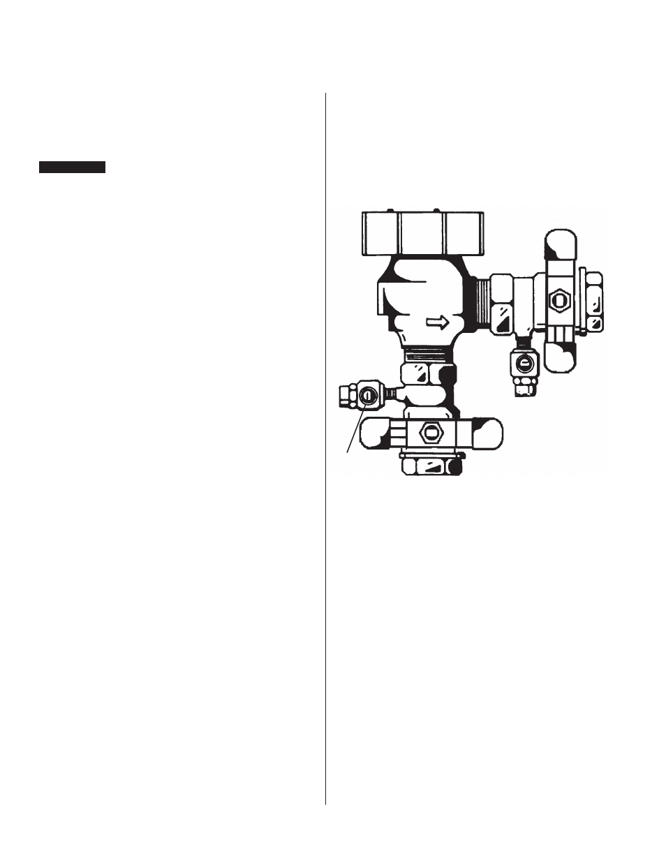
Test Cock No. 1
Test Cock No. 2
800M4-QT/LF800M4-QT
Test Procedure for Pressure Vacuum Breakers