Qual and rsl test cable, 10 qual and rsl test cable – BridgeWave AR60X User Manual
Page 33
AR60X Installation Manual
27
58000517, rev B
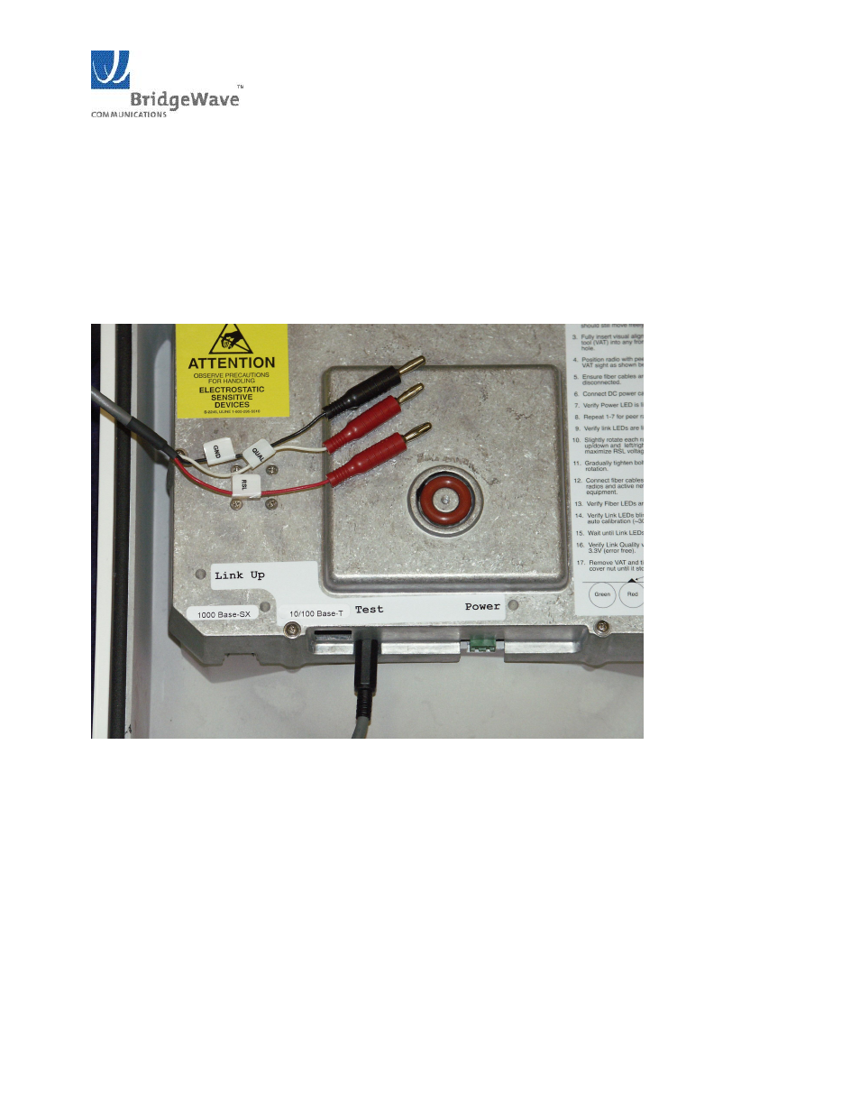
3.10 QUAL and RSL Test Cable
The alignment procedure is optimized through the use of the provided test cable. This test cable is
designed for use with a digital voltmeter (not provided) to read the Link Quality and Receive Signal
Level (RSL) voltage generated by the radio’s receiver.
1.
To read the RSL value of the radio, insert GND (ground) and RSL banana plugs into the
voltmeter. Note the RSL voltage. The voltage may be fluctuating; in this case, note the
maximum value seen.
Figure 315: Top view of test cable provided to check Link Quality & Receive Signal level
2.
To read the Link Quality value of the radio, insert GND (ground) and QUAL banana plugs into
the voltmeter. Note the Link Quality voltage. After the radios have performed an auto calibration
the quality voltage should read 3.3V if the link is aligned on the main antenna beam and there
are no obstructions (i.e., trees, buildings, etc…) in the path, the link distance is within the
operating parameters of the radio (see Section 2.4 above), and it is not raining heavily. AR
radios may have less than 3.3V Quality in 1000 Mbps mode and still operate normally; this
would indicate that the AR link is operating near the distance limit for Gigabit Ethernet
performance.