Specifications, Performance curves – Banner U-GAGE QT50U DC Series—Analog User Manual
Page 9
Specifications
Supply Voltage and Current
10 to 30 V dc (10% maximum ripple)
100 mA max at 10 V, 40 mA max at 30 V (exclusive of load)
Sensing Range
200 mm to 8 m (8 inches to 26 feet)
Ultrasonic Frequency
75 kHz burst, rep. rate 96 ms
Supply Protection Circuitry
Protected against reverse polarity and transient overvoltages
Output Protection
Protected against short circuit conditions
Delay at Power-up
1.5 seconds
Analog Output Configuration (Voltage Sourcing: 0 to 10 V dc)
Minimum Load Resistance = 500 ohms
Minimum Required Supply Voltage for Full 0-10 V Output Span =
(1000/RLoad + 13) V dc
Analog Output Configuration (Current Sourcing: 4 to 20 mA)
Maximum Load Resistance = 1 kΩ or ( Vsupply/0.02 - 5) ohms,
whichever is lower
Minimum required supply voltage for full 4-20 mA output span = 10 V
dc or [(RLoad × 0.02) + 5] V dc, whichever is greater.
4 to 20 mA output calibrated at 25 °C with a 250 Ω load.
Temperature Effect
Uncompensated: 0.2% of distance/°C
Compensated: 0.02% of distance/°C
Linearity
+/- 0.2% of span from 200 to 8000 mm
+/- 0.1% of span from 500 to 8000 mm (1 mm minimum)
Resolution
1.0 mm
Output Response Time
100 ms to 2300 ms
See DIP Switches 5 and 6
Minimum Window Size
20 mm
Adjustments
Sensing window limits: TEACH-Mode programming of near and far
window limits may be set using the push buttons or remotely via
TEACH input.
Indicators
Green Power On LED: Indicates power is ON
Red Signal LED: Indicates target is within sensing range, and the
condition of the received signal
Teach/Output indicator (bicolor Amber/Red): Amber – Target is within
taught limits; Flashing Amber – Target is outside taught window limits;
Red – Sensor is in TEACH mode
Remote TEACH
To Teach: Connect gray or yellow wire to 0 to 2 V dc; impedance 12 kΩ
Construction
Transducer: Ceramic/Epoxy composite
Housing: ABS/Polycarbonate
Membrane Switch: Polyester
Lightpipes: Acrylic
Operating Conditions
Temperature: –20 °C to 70 °C (–4 °F to 158 °F)
Maximum relative humidity: 100%
Connections
2 m (6.5 ft) or 9 m (30 ft) shielded 5-conductor (with drain) PVC
jacketed attached cable or 5-pin Euro-style quick-disconnect or 5-pin
Mini-style quick-disconnect
Environmental Rating
Leakproof design is rated IEC IP67; NEMA 6P
Vibration and Mechanical Shock
All models meet Mil Std. 202F requirements. Method 201A (vibration:
10 to 60Hz max., double amplitude 0.06", maximum acceleration 10G).
Also meets IEC 947-5-2 requirements: 30G 11 ms duration, half sine
wave
Temperature Warmup Drift
Less than 0.8% of sensing distance upon power-up with Temperature
Compensation enabled (see Temperature Compensation)
Application Notes
Objects passing inside the specified near limit (200 mm) may produce
a false response.
Certifications
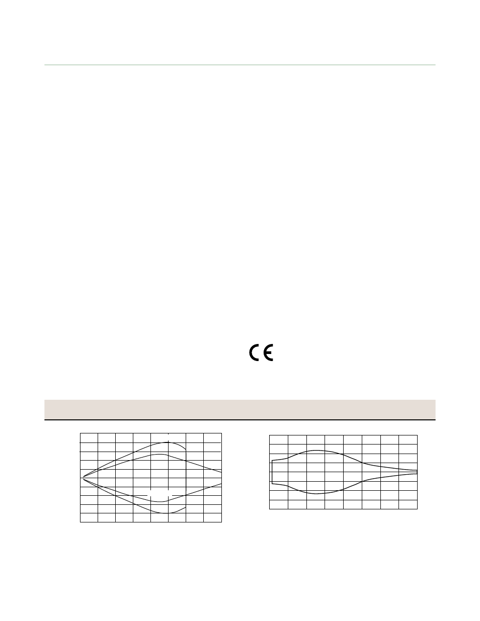
Performance Curves
QT50U Effective Beam Pattern
QT50U (with 500 mm Plate) Maximum Target
Rotation Angle
Effective Beam W
idth
Target Distance
-200 mm
-400 mm
-600 mm
200 mm
400 mm
0
600 mm
800 mm
1000 mm
-800 mm
-1000 mm
0
1 m
(3.3')
2 m
(6.6')
3 m
(9.8')
4 m
(13.1')
5 m
(16.4')
6 m
(19.6')
7 m
(22.9')
8 m
(26.2')
8"
-8"
0
16"
-16"
24"
-24"
31"
-31"
-40"
40"
25 mm Rod
500 mm Plate
-10
-20
-30
10
0
20
30
40
-40
0
Target Distance (m)
Target Rotation (deg)
1 m
(3.3’)
2 m
(6.6’)
3 m
(9.8’)
4 m
(13.1’)
5 m
(16.4’)
6 m
(19.6’)
7 m
(22.9’)
8 m
(26.2’)
U-GAGE QT50ULB Series Sensors with Analog Output
P/N 70137 Rev. B
www.bannerengineering.com - tel: 763-544-3164
9