Sensor programming – Banner U-GAGE QT50U DC Series—Analog User Manual
Page 4
Switches 5 and 6 are used to set the speed of the output response. The four values for response speed relate to the
number of sensing cycles over which the output value is averaged.
Switch 7: Temperature Compensation
ON = Temperature compensation enabled
OFF = Temperature compensation disabled
Changes in air temperature affect the speed of sound, which in turn affects the distance reading measured by the sensor.
An increase in air temperature shifts both sensing window limits closer to the sensor. Conversely, a decrease in air
temperature shifts both limits farther away from the sensor. This shift is approximately 3.5% of the limit distance for a 20
°C change in temperature. With temperature compensation enabled (Switch 7 ON), the sensor will maintain the window
limits to within 1.8 percent over the –20 °C to 70 °C range.
The temperature sensor in the sensor’s bezel cannot adapt to temperature change as quickly as an external temperature
device can. When there are fast fluctuations in temperature, it may be best to use an external temperature monitor and
feed its signal and the uncompensated distance measurement into a controller and perform the compensation calculations
within the controller.
Consult the factory for details on performing temperature compensation calculations.
•
If temperature compensation is enabled, exposure to direct sunlight can affect the sensor’s ability to accurately
compensate for changes in temperature.
•
With temperature compensation enabled, the temperature warmup drift upon power-up is less than 0.8% of the
sensing distance. After 15 minutes, the apparent distance will be within 0.5% of the actual distance. After 30
minutes, the apparent distance will be within 0.3% of the actual distance.
Switch 8: Factory Calibration
ON = Factory calibration only
OFF = Normal operation
U-GAGE
MIN
SIGNAL
TM
MAX
POWER
ANALOG
WINDOW
LIMIT
MIN
ANALOG
MAX
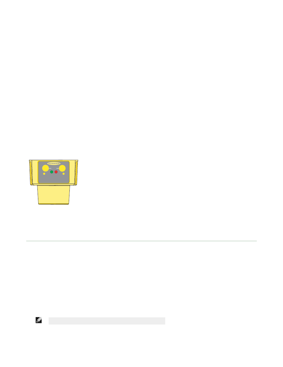
Figure 4. Sensor Features
MIN - Minimum limit indicator
MAX - Maximum limit indicator
POWER - Sensor power indicator
SIGNAL - Target signal strength indicator
General Notes on Programming
•
The sensor returns to RUN mode if the limit is not registered within 120 seconds after entering TEACH Mode.
•
Press and hold the programming push button for more than 2 seconds (before teaching the limit) to exit PROGRAM
mode without saving any changes. The sensor will revert to the last saved program.
•
If the push buttons do not respond, perform a remote lockout procedure to enable push buttons.
Sensor Programming
Two TEACH methods may be used to program the sensor:
•
Teach individual minimum and maximum limits
•
Use the Auto-Window feature to center a sensing window around the taught position
The sensor may be programmed either via its two push buttons, or via a remote switch. Remote programming also may be
used to disable the push buttons, preventing unauthorized personnel from adjusting the programming settings. To access
this feature, connect the gray wire of the sensor to 0–2 V dc, with a remote programming switch between the sensor and
the voltage.
NOTE: The impedance of the Remote Teach input is 12 kΩ.
Programming is accomplished by following the sequence of input pulses. The duration of each pulse (corresponding to a
push button “click”), and the period between multiple pulses, are defined as “T” where 0.04 seconds < T < 0.8 seconds.
U-GAGE QT50ULB Series Sensors with Analog Output
4
www.bannerengineering.com - tel: 763-544-3164
P/N 70137 Rev. B