Analog output slope, Configuration, Ft/s – Banner U-GAGE QT50U DC Series—Analog User Manual
Page 2
In metric
units:
C
m/s
= 20 √273 + T
C
In English units:
ft/s
= 49 √460 + T
F
C
C
m/s
= speed of sound in meters per second
C
ft/s
= speed of sound in feet per second
T
C
= temperature in °C
T
F
= temperature in °F
The speed of sound changes roughly 1% per 6° C (10° F). QT50U series ultrasonic sensors have temperature
compensation available, via the 8-pin DIP switch. Temperature compensation will reduce the error due to temperature by
about 90%.
NOTE: NOTE: If the sensor is measuring across a temperature gradient, the compensation will be less
effective.
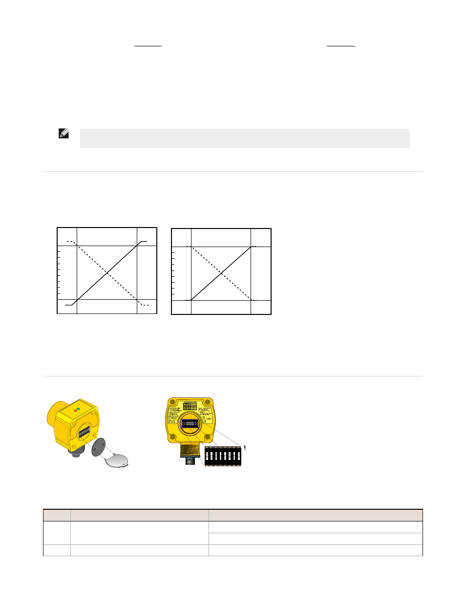
Analog Output Slope
The U-GAGE QT50ULB Sensor may be programmed for either a positive or a negative output slope, depending on which
conditions are taught for the Min and Max Analog limits. If the Min Analog limit is the Near Window setting and the Max
Analog limit is the Far Window setting, then the slope will be positive. If the opposite is true, then the slope will be
negative.
Current-Sourcing Models
Target Position
Positive
Slope
Near
Window
Far
Window
Analog Output (mA)
20
4
Negative
Slope
Voltage-Sourcing Models
Target Position
Positive
Slope
Near
Window
Far
Window
Voltage Output (V dc)
10
0
Negative
Slope
Figure 1. Positive and Negative Output Slops
Configuration
3
ON
DIP
Figure 2. Removing the Access Cover
1 2 3 4 5 6 7 8
ON
DIP
1 2 3 4 5 6 7 8
ON
DIP
ON Position
Figure 3. DIP Switch Location
The U-GAGE QT50ULB Sensor features an
8-pin DIP switch bank for user setup. The
DIP switches are located behind the access
cover on the back of the sensor as shown. A
spanner tool is included with each sensor
for removing the cover.
Switch Function
Settings
1
Voltage/Current Mode
ON = Current mode: 4 to 20 mA
OFF* = Voltage mode: 0 to 10 V dc
2
Loss of Echo
ON* = Min-Max Mode
U-GAGE QT50ULB Series Sensors with Analog Output
2
www.bannerengineering.com - tel: 763-544-3164
P/N 70137 Rev. B