Multi-beam, Wire power blocks, Hookup diagrams for 2-wire power blocks – Banner MULTI-BEAM Series User Manual
Page 28: Basic hookup of 2-wire multi-beam
L1
L2
1
2
2PBA
2PBB
2PBD
V ac
(See Specifications)
I
N
P
U
T
S
P
r
o
g.
C
r
t
l.
neutral
1
2
3
4
5
6
7
8
Hookup
typical
for all
8 inputs
AC "hot"
AC neutral
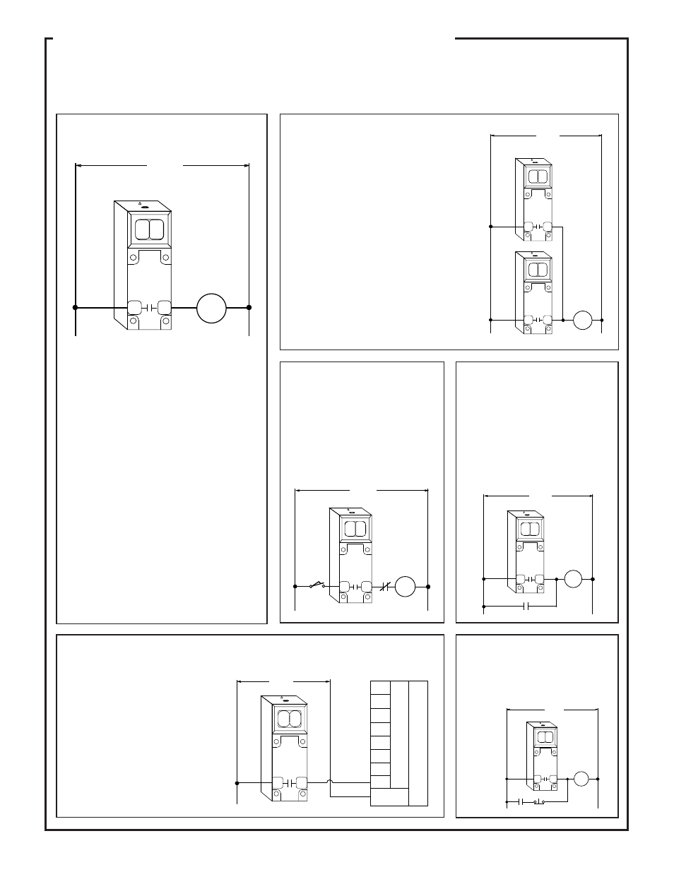
Hookup Diagrams for 2-wire Power Blocks
(except models 2PBR & 2PBR2; see page 27)
NOTE: output has maximum load capacity of 3/4 amp; maximum resistive load 15K ohms, minimum inductive load 1.2 watts (10mA)
1CR relay will latch "on" whenever the 2-wire
MULTI-BEAM output is energized. 1CR is reset
when the normally-closed pushbutton switch is
pressed.
MULTI-BEAM 2-wire sensors operate with very
low (1 milliamp) off-state leakage current. As a
result, they will interface directly to most PLCs
without the need for an artificial load resistor. If
the off-state voltage (1mA x input resistance of
the PLC) is higher than the PLC sensing thresh-
old, install a 10K
Ω
to 15K
Ω
, 5-watt resistor for
each 2-wire sensor. The resistor connects be-
tween the input terminal and ac neutral.
If you have a question on hookup to a specific
brand of PLC, contact the Banner Applications
Department during normal business hours.
V ac
(See Specifications)
L1
L2
2PBA
2PBB
2PBD
1
2
2PBA
2PBB
2PBD
1
2
LOAD
L1
L2
2PBA
2PBB
2PBD
1
2
V ac
(See Specifications)
LOAD
L1
L2
2PBA
2PBB
2PBD
1
2
V ac
(See Specifications)
LOAD
RESET
L1
L2
2PBA
2PBB
2PBD
1
2
V ac
(See Specifications)
1CR
1CR
LATCH
MULTI-BEAM 2-wire sensors wire in series with an appropri-
ate load. This combination, in turn, wires directly across the ac
line. A 2-wire sensor may be connected exactly like a mechani-
cal limit switch.
The MULTI-BEAM remains powered when the load is "off" by
a residual current which flows through the load. This off-state
leakage current is always less than 1 milliamp. The effect of this
leakage current depends upon the characteristics of the load. The
voltage which appears across the load in the off-state is equal to
the leakage current of the sensor multiplied by the resistance of
the load:
V (off)= 1mA x R(load)
If this resultant off-state voltage is less than the guaranteed turn-
off voltage of the load, the interface is direct. If the off-state
voltage causes the load to stay "on", an artificial load resistor
must be connected in parallel with the load to lower its effective
resistance. Most loads, including most programmable logic
controller (PLC) inputs, will interface to 2-wire sensors with
1mA leakage current without the need for an artificial load
resistor. There is no polarity requirement. Either wire may
connect to terminal #1, and the other to terminal #2.
CAUTION: all three components of a MULTI-BEAM 2-wire
sensor will be destroyed if the load becomes a short circuit!!
V ac
(See Specifications)
L1
L2
LOAD
2PBA
2PBB
2PBD
1
2
Basic Hookup of 2-wire MULTI-BEAM
Multiple 2-wire MULTI-BEAMs may be wired together in
parallel to a load for "OR" or "NAND" logic functions.
When sensors are wired in parallel, the off-state leakage
current through the load is equal to the sum of the leakage
currents of the individual sensors. Consequently, loads with
high resistance, like small relays and electronic circuits, may
require artificial load resistors.
2-wire MULTI-BEAM sensors have a 100 millisecond
power-up delay for protection against false outputs. When
2-wire MULTI-BEAMs are wired together in parallel, any
power block which has an energized output will rob all of the
other power blocks of the current they need to operate.
When the energized output drops, there will be a 0.1 second
delay before any other MULTI-BEAM can energize. As a
result, the load may momentarily drop out.
2-wire MULTI-BEAM sensors cannot wire in series with
other 2-wire sensors unless power block model 2PBR is
used. If series connection of 2-wire ac sensors is required,
consider models within the VALU-BEAM or MINI-BEAM
families.
2-wire MULTI-BEAMs in Parallel
2-wire MULTI-BEAM
in Series with Contacts
2-wire MULTI-BEAM
in Parallel with Contacts
When 2-wire MULTI-BEAM sensors are con-
nected in series with mechanical switch or relay
contacts, the sensor will receive power to operate
only when all of the contacts are closed. The
false-pulse protection circuit of the MULTI-
BEAM will cause a 0.1 second delay between the
time that the last contact closes and the time that
the load can energize.
2-wire MULTI-BEAM sensors may be wired in
parallel with mechanical switch or relay con-
tacts. The load will energize when any of the
contacts close or the sensor output is energized.
When a contact is closed, it shunts the operating
current away from the MULTI-BEAM. As a
result, when all of the contacts are open, the
MULTI-BEAM's 0.1 second power-up delay
may cause a momentary drop-out of the load.
Photoelectric Latch with
Manual Reset
Hookup of 2-wire MULTI-BEAM to a Programmable Logic Controller (PLC)
MULTI-BEAM
2-wire Power Blocks
28