R55 expert, Color mark sensors, Lens location – Banner R55E Series User Manual
Page 8: Mounting the sensor, Mounting considerations
R55
Expert
™
Color Mark Sensors
8
P/N 59574 rev. B
Banner Engineering Corp. • Minneapolis, MN U.S.A.
www.bannerengineering.com • Tel: 763.544.3164
90º
Roller or
Tension Bar
Opaque,
Non-reflective
Web Material
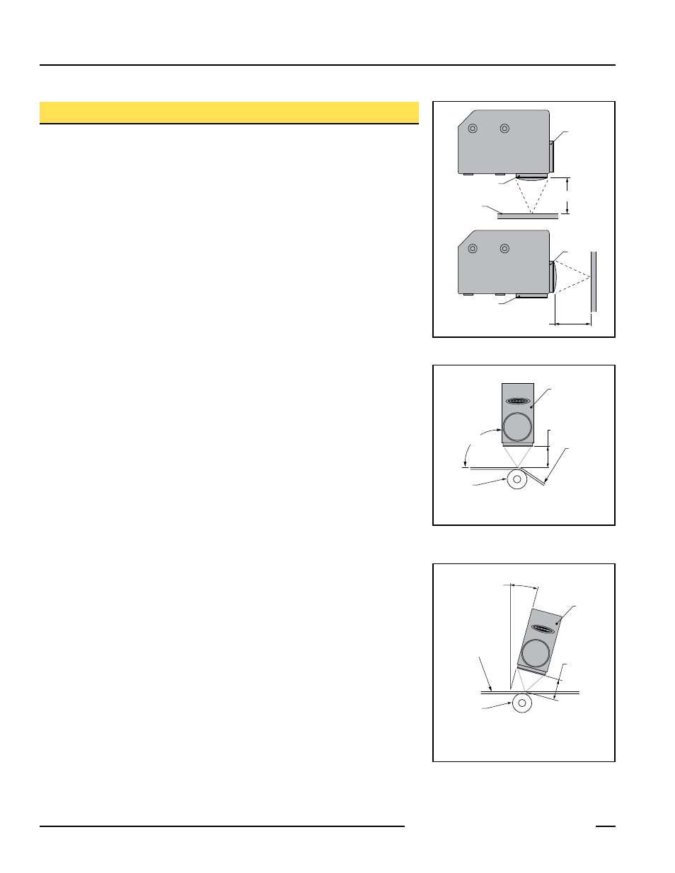
Focus Distance
10.0 mm (0.39")
R55E
Mount the R55E perpendicular to
non-reflective (matte) materials
Approximately 15º
Focus Distance
10.0 mm (0.39")
Mount the R55E at approximately 15°
from perpendicular to transparent
and opaque reflective materials
Roller or
Tension Bar
Transparent or
Opaque Reflective
Web Material
R55E
Figure . Mounting for sensing opaque
non-reflective materials
Figure 8. Mounting for sensing opaque
reflective and transparent
materials
Installation Notes
Lens Location
The lens of the R55E may be installed at either of two lens ports (see Figure 6). The lens
and the lens port cap are both threaded and may be exchanged by hand; no tools are
required. The lens and cap both include an o-ring seal.
NOTE: Lens port cap must be installed for reliable operation.
Mounting the Sensor
The R55E includes a total of eight M5 threaded holes used for mounting (see dimension
drawing on page 10). These threaded holes are positioned to match the mounting hole
patterns common to other color mark sensors. The R55E includes four
M5 x 0.8 x 6 mm stainless steel cap screws and a hex key wrench.
The R55E focus is located at 10 mm (0.39") ahead of the lens surface. The R55E must
be mounted within 3 mm (0.12") of this distance from the surface of the material for
reliable sensing (Figure 7).
Mounting Considerations
1. Whenever possible, it is a good idea to sense a web material at a location where it
passes over a tension bar or roller, to minimize the adverse effects of web “flutter” or
sag (Figure 7).
2. When sensing a color mark on a reflective (shiny) material, mount the R55E at
an angle that places the lens centerline at approximately 15° off perpendicular to
the material’s surface (see Figure 8). This “skew angle” will minimize strong direct
reflections (which tend to overwhelm the sensor), and allow the sensor to discern the
relatively small optical contrast offered by difference in colors.
3. Clear materials are poor reflectors of light. When sensing a mark printed on a clear
material (e.g., a clear poly web), position a reflective surface directly behind the clear
material that will return light to the R55E. The printed mark, regardless of its color,
then becomes the dark condition, as it blocks the light from reaching the reflective
surface. Most clear materials are also shiny; it is important also to include a 15° skew
angle when sensing clear materials (Figure 8).
Lens
Cap
10 ± 3 mm
Cap
Surface of
Material
Lens
10 ± 3 mm
Figure . R55E Lens Positions