Maxi-beam, Power blocks and wiring base, Rpbr – Banner MAXI-BEAM Series User Manual
Page 9: Ac/dc model functional schematic, Hookup diagrams for rpbt and rpbt-1 power blocks, Connections, Application caution, Continued), Hookup to micro-amp logic (mps-15 chassis), Power block models rpbr and rpbr2
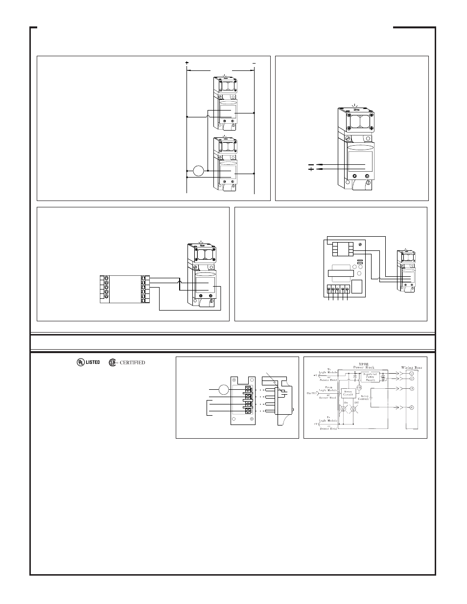
RPBR
INPUT: 12 to 30V dc, 40mA, exclusive of load current
(at 30V dc); or 12 to 250V ac, 50/60Hz.
OUTPUT: SPST electromechanical relay contact.
Contact rating: 250V ac max., 30V dc max., 5 amps
max. (resistive load); install MOV across contact if
switching inductive load. Contact response: 20ms
open and close (NOTE: add to sensor head response).
Mechanical life: 10,000,000 operations.
OPERATING TEMPERATURE: -40 to +50 de-
grees C (-40 to +122 degrees F).
4
3
2
1
12 to 250V ac
12 to 30V dc
LOAD
250V ac max.
30V dc max.
5 amps max.
RPBR
Dry Contact
Model RPBR operates the MAXI-BEAM with either ac or dc. It offers an SPST "hard" relay contact
between wiring base terminals #3 & #4, which allows the MAXI-BEAM sensor to directly interface with
loads which draw high current. It also allows series connection ("AND" logic) with multiple dc sensors.
AC/DC Model
Functional Schematic
4
3
2
1
RPBT
CL3RA
CL3RB
CL5RA
CL5RB
8
7
6
5
4
9
10
11
1
2
3
RPBT
RPBT
4
3
1
2
10 - 30V dc
4
3
1
2
LOAD
Parallel Hookup of RPBT Power Blocks
to a Common Load
Any number of MAXI-BEAMs may be connected in
parallel to a load to create "LIGHT-OR" (light oper-
ate mode) or "DARK-OR" (dark operate mode) mul-
tiple sensor logic. The diagram at the right shows the
current sinking outputs of two MAXI-BEAMs con-
nected in parallel to control a load which requires a
current sink (power block terminal #3). For loads
requiring a current source, connect the wires from the
load instead between terminals #4 and #2 (common).
NOTE: series connection of dc MAXI-BEAM sen-
sors may be accomplished using power block model
RPBR (see below).
MAXI-BEAM emitter only sensor heads use dc power block model
RPBT-1, which connects directly across the dc supply as shown.
The current sinking output of MAXI-BEAM power block
RPBT may be connected directly to the input of CL Series
MAXI-AMP modules. A MAXI-AMP which is powered
by ac voltage offers a dc supply with enough capacity to
power one MAXI-BEAM sensor, as is shown in this
hookup diagram. When an emitter/receiver pair is used,
the emitter should be
powered from a sepa-
rate power source
(e.g.- use power block
RPBA-1, etc.).
Hookup to MAXI-AMP Logic Module
Hookup of
a DC Emitter
RPBT-1
10 - 30V dc
4
3
1
2
MAXI-BEAM
Power Blocks and Wiring Base
9
Hookup Diagrams for RPBT and RPBT-1 Power Blocks
(continued)
Relay
120
Vac
N
O
C
N
C
MODEL MPS-15
7
8
1
2
6
5
4
3
NO
NC
Micro-
Amp
Logic
4
3
1
2
RPBT
The current sinking output of an
RPBT power block may be con-
nected directly to the primary input
(terminal #7) or the other inputs of
MICRO-AMP logic modules. The
following logic modules may be
used:
MA4-2
One shot
MA5
On/off delay
MA4G
4-input "AND"
MA4L
Latch
Hookup to MICRO-AMP Logic (MPS-15 Chassis)
Connections
Power block modules RPBR and RPBR2 use "partial phase firing" power
conversion to enable their wide range of ac input voltage (12 to 250V ac).
AC power is applied to the sensor for only a small portion of each ac half-
cycle. The current demand during this period may be as high as 1 to 2
amps per sensor.
The collective current demand of several of these sensors on a common
ac line is significant. If several sensors are wired directly to the ac mains,
it is unlikely that any adverse effects will be noticed. On the other hand,
problems may be noticed if several sensors are connected to a common
circuit that is isolated from the ac mains by a transformer. The collective
peak current demand may rob other components on the same circuit of
enough power to function properly. In the worst case, a transformer with
inadequate reserve current capacity may overheat. Barring a transformer failure, the
sensors themselves will operate normally.
As a general rule, if more than three or four MAXI-BEAM sensors using RPBR or RPBR2
power blocks must be connected to the same transformer-isolated ac circuit, consider the
substitution of power block model RPBAR2 (for 105-130V ac) or model RPBBR2 (for
210-250V ac), which use conventional ac-to-dc power conversion circuitry. These power
blocks connect exactly like model RPBR2, but do not exhibit the peak power demand of a
phase-fired design. Output relay specifications are identical to model RPBR2. Contact
your Banner representatiove or distributor for pricing and availability.
NOTE: Peak power demand is not an issue when the RPBR or RPBR2 are powered from
direct current (12 to 30V dc).
Application caution:
power block models RPBR and RPBR2