Sensor heads, Programming the maxi-beam sensor head, Sensing mode models beam pattern – Banner MAXI-BEAM Series User Manual
Page 7: Excess gain, Rsbfv, Maxi-beam, Fiber optic mode (glass fibers)
RSBFV
OPPOSED
MODE
10
1
DISTANCE
100
1000
.1 IN
1 IN
10 IN
100 IN
Opposed mode
IT23S fibers
IT13S fibers
RSBFV
E
X
C
E
S
S
G
A
I
N
I
10
1
DISTANCE
100
1000
.1 IN
1 IN
10 IN
100 IN
RSBFV
with L9 lens
and BT13S
fibers
with L16F
lens and
BT13S
fibers
Retroreflective mode
w/BRT-3 reflector
E
X
C
E
S
S
G
A
I
N
I
10
1
DISTANCE
100
1000
.1 IN
1 IN
10 IN
Range based on 90% reflectance
white test card.
BT23S fibers
BT13S
fibers
RSBFV
Diffuse mode
.01 IN
E
X
C
E
S
S
G
A
I
N
I
.2
.4
0
0
.025
.8
1.0
.050
.075
.1
.025
.050
.075
.1
.6
BT23S
BT13S
Diffuse mode
I
N
C
H
E
S
DISTANCE TO 90% WHITE TEST CARD--INCHES
RSBFV
4
8
12
16
20
0
0
2
4
6
2
4
6
w/L9 lens w/L16F lens
I
N
C
H
E
S
DISTANCE TO REFLECTOR--INCHES
BT13S fiber, retroreflective
mode, with BRT-3 reflector
RSBFV
2
4
6
8
10
0
0
1
2
3
1
2
3
IT13S
IT23S
Opposed mode
I
N
C
H
E
S
OPPOSED DISTANCE--INCHES
RSBFV
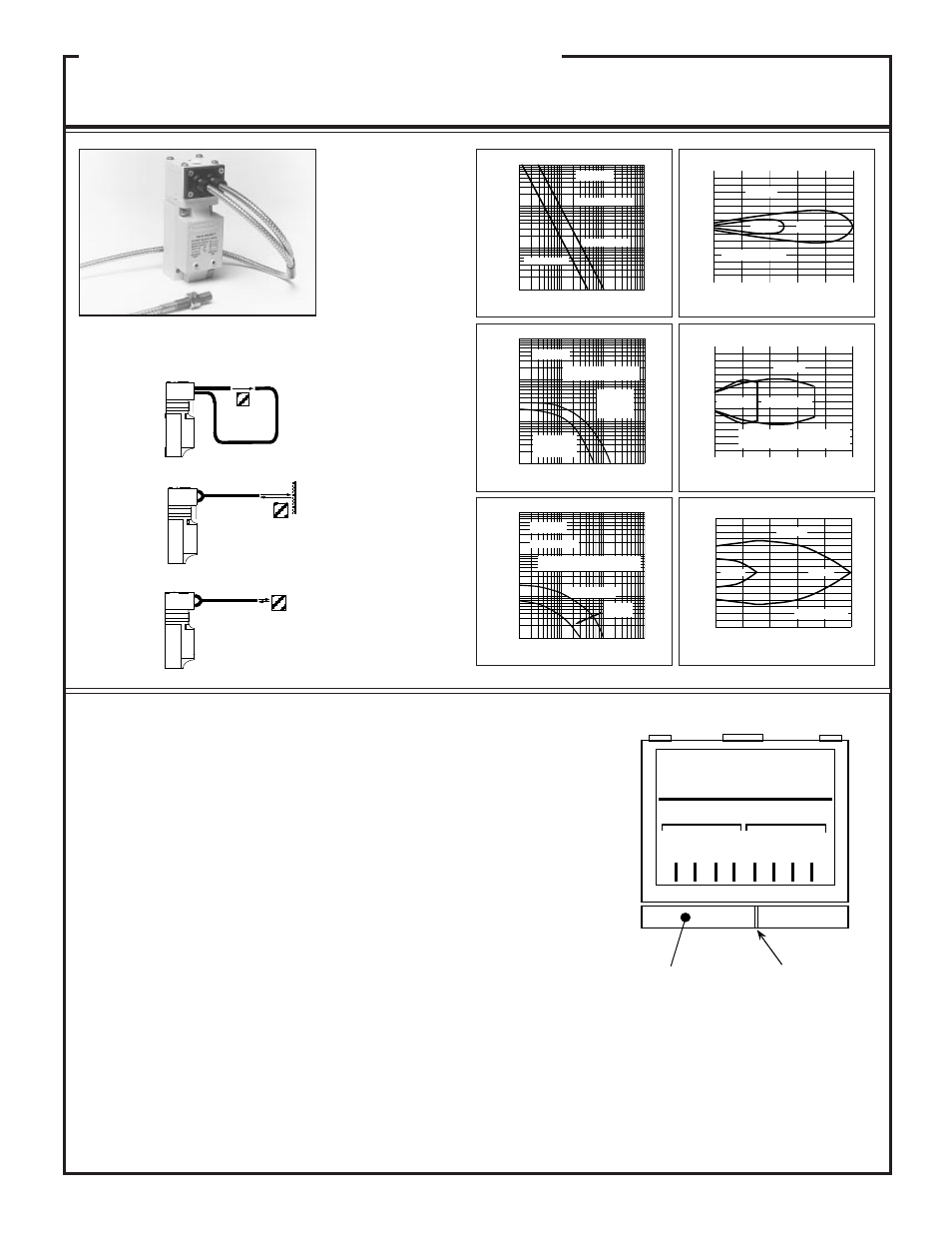
Programming the MAXI-BEAM Sensor Head
MAXI-BEAM sensor heads may be programmed for sensor response time (and range) and for
LIGHT/DARK operate. Each sensor head is supplied with a programming ring which attaches
below the the sensor head by a system of pegs. There are four programming notches around the
perimeter of the ring. To program the sensor head, simply find the notch which will line up with
the desired program combination (see diagram, right). NOTE: the programming ring may have
to be turned upside-down in order to line up the notch with the program. If LIGHT OPERATE
is selected, the MAXI-BEAM output will energize on a dark-to-light transition. If DARK
OPERATE is selected, the MAXI BEAM output will energize on a light-to-dark transition. In
the illustration, the MAXI-BEAM is set for high speed (HS) operation in the LIGHT OPERATE
output state. See the information about each individual sensor head for the response time and
range associated with each setting (HP, 2W, HS, SP). NOTE: when programming the RSBE,
RSBSER, or RSBEF emitter, select the mode which is programmed for the receiver. EXCEP-
TION: if the receiver is programmed for the 2-wire (2W) mode, select high power (HP) on the
emitter.
Range: see excess gain
curves
Beam: visible red, 650nm.
Response:
HS mode only, 1ms on/off
Repeatability:
HS = 0.3ms
Sensing Mode
Models
Beam Pattern
MAXI-BEAM
HS: HI SPEED
HP: HI POWER
2W: 2 WIRE
SP: SPECIAL
DARK
OPERATE
LIGHT
OPERATE
H
S
S
P
2
W
H
P
H
S
S
P
2
W
H
P
Programming ring
Notch
MAXI-BEAM
Sensor Heads
OBJECT
OBJECT
RETROREFLECTOR
OBJECT
RETRO
MODE
DIFFUSE
MODE
FIBER OPTIC Mode
(glass fibers)
Excess Gain
7
Model RSBFV is a
visible-light sensor head
designed for use with
glass fiber optics. It is
compatible with all
standard Banner glass
fiber optic assemblies
(see Banner product
catalog). In order to
function properly, the
RSBFV must be
programmed for the
"HS" response mode.
The RSBFV is not for
use with plastic fiber
optics (instead use
RSBFP).
The model RSBFV will
function only when
programmed for the "HS"
response mode.
The model RSBFV will
not operate with 2-wire
power blocks (models
R2PBA and R2PBB).