Maxi-beam, Power blocks and wiring base, Rpbt rpbt-1 – Banner MAXI-BEAM Series User Manual
Page 8: Hookup diagrams for rpbt and rpbt-1 power blocks, Dc models connections, Functional schematic, For emitters)
The hookup shown is typical for all inputs.
Hookup shown
is typical for
all inputs
4
3
1
2
RPBT
+10 - 30V dc
1
2
3
4
5
6
7
8
dc+
dc com
I
N
P
U
T
S
P
r
o
g.
C
t
r
l.
4
3
1
2
RPBT
+10 - 30V dc
1
2
3
4
5
6
7
8
dc+
dc com
I
N
P
U
T
S
P
r
o
g.
C
t
r
l.
Hookup shown
is typical for
all inputs
4
3
1
2
RPBT
10 - 30V dc
(-) dc
* Use pullup resistor to
logic supply
*
+5V to 30V dc
Logic Supply
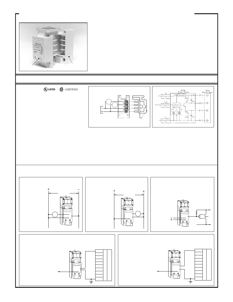
Hookup Diagrams for RPBT and RPBT-1 Power Blocks
Hookup to dc Relay or Solenoid
(using sourcing output)
Hookup to dc Relay or Solenoid
(using sinking output)
Hookup to Logic Gate
(using sinking output)
Hookup to a Programmable Controller
requiring a current source
Hookup to a Programmable Controller
requiring a current sink
A logic zero (0 volts dc) is applied to the GATE input
when the MAXI-BEAM sinking output is energized.
When de-energized, a logic one is applied. The logic
Use MAXI-BEAM PNP output
(terminal #4) to interface to
PLCs and other logic devices
requiring a current source at the
inputs. Connect terminal #4 of
the power block to any input of
the PLC. Connect the negative
of the MAXI-BEAM power
supply (terminal #2) to the
negative of the PLC power sup-
ply.
The hookup shown is typical for all inputs.
INPUT: 10 to 30V dc, 20mA, exclusive of load cur-
rent; 10% maximum ripple.
OUTPUT: one open-collector NPN (current sinking)
and one open-collector PNP (current sourcing) transis-
tor. 250mA continuous, short-circuit and reverse po-
larity protected (both outputs).
ON-STATE VOLTAGE DROP:
PNP output: less than 1 volt at 10mA and less than 2
volts at 250mA.
NPN output: less than 200 millivolts at 10mA and less
than 1 volt at 250mA.
OFF-STATE LEAKAGE CURRENT: less than 10
microamps.
RPBT
RPBT-1
(for emitters)
When using the
power block with
current sinking
(NPN) output, simple
loads connect be-
tween terminal #3
and the positive sup-
ply (terminal #1).
When using the
power block with cur-
rent sourcing (PNP)
output, simple loads
connect between ter-
minal #4 and dc com-
mon (terminal #2).
Use MAXI-BEAM NPN out-
put (terminal #3) to interface to
PLCs and other logic devices
requiring a current sink at the
inputs. Connect terminal #3 of
the power block to any input of
the PLC. Also connect the
negative of the MAXI-BEAM
power supply (terminal #2) to
the negative of the PLC power
supply.
supply must be
common to the
M A X I - B E A M
supply negative.
Power block RPBT is the one most often used in low voltage dc applications. There are two
solid state output switches (transistors), each rated at 1/4 amp. The NPN output at terminal #3
of the wiring base sinks current to the negative side of the power supply. The PNP output at
terminal #4 sources current to the load from the positive side of the power supply. Both outputs
may be used simultaneously. Response time of a MAXI-BEAM which uses model RPBT is
the response time which is programmed at the sensor head (plus logic delays, if any). Model
RPBT-1 is the dc power block to use with model RSBE, RSBESR, and RSBEF emitter sensor
heads. The RPBT-1 has no switching elements.
DC Models
Connections
4
3
1
2
RPBT
10 - 30V dc
LOAD
4
3
1
2
RPBT
10 - 30V dc
LOAD
MAXI-BEAM
Power Blocks and Wiring Base
4
3
2
1
10-30V dc
LOAD
Source
LOAD
Sink
RPBT
MAXI-BEAM power blocks provide regulated low voltage dc power to the sensor head and
logic module (if one is used), and all power blocks (except emitter-only types) contain an
output switch for interfacing to loads or to control circuitry.
Power blocks plug into the model RWB4 wiring base which has heavy-duty screw
terminals that accept up to #12 gauge wire (no lugs are necessary). The RWB4 wiring base
is necessary for all MAXI-BEAM sensor assemblies (except sensors using the RPBTLM
power block), and must be purchased separately.
All power blocks, except the emitter-only types, include status LEDs which continuously
indicate the state of the output circuit and input power. MAXI-BEAM power blocks are
epoxy-encapsulated and rated for -40 to +70 degrees C (except models RPBR and RPBR2).
All MAXI-BEAMs have circuitry to prevent false closure of the output on power-up.
8
Power Block
RWB4 Wiring Base
(order separately)
Functional Schematic