Maxi-beam, Maxi-beam accessories, Logic modules – Banner MAXI-BEAM Series User Manual
Page 15: Rlm8, Model and logic functions, Program definition, Programming, Replacement upper covers (lens assemblies)
Model and Logic Functions
RLM8
Lens Interchangeability
Replacement Upper Covers (Lens Assemblies)
RSBE ....................................... RUC-L
RSBR ....................................... RUC-L
RSBLV .................................... RUC-L
RSBLVAG .............................. RUC-AG
RSBD ...................................... RUC-L
RSBDSR, ESR, & RSR ........... RUC-D
RSBC, CV ............................... RUC-C
RSBF, FV ................................ RUC-F
RSBFP ..................................... RUC-FP
MAXI-BEAM Accessories
USE UPPER
COVER
RSBLV to RSBLVAG ... RUC-AG
RSBLV to RSBCV ......... RUC-C
RSBD to RSBDSR ......... RUC-D
RSBD to RSBF ............... RUC-F
RSBDSR to RSBF .......... RUC-F
RSBLVAG to RSBLV ... RUC-L
RSBCV to RSBLV ......... RUC-L
RSBDSR to RSBD ......... RUC-L
RSBF to RSBDSR .......... RUC-D
Replacement Lenses
CONVERSION
FROM - TO
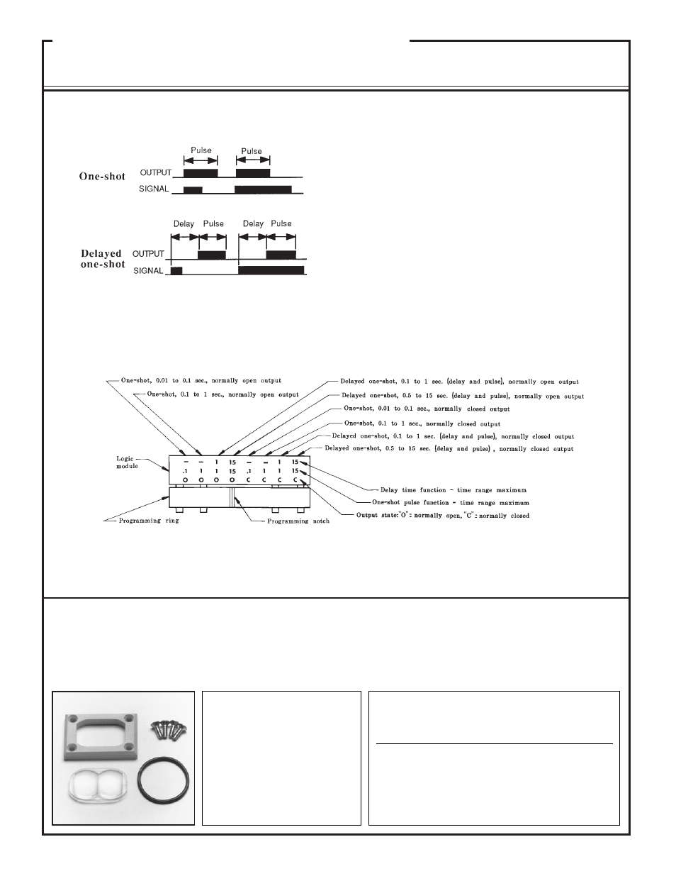
Program Definition
MAXI-BEAM
Logic Modules
Programming
15
An upper cover consists of the optical element for the MAXI-BEAM sensor head. An upper cover may be used as a replacement part or for
modifying the optical response of a sensor. Upper cover assemblies include lens, replacement bezel, o-ring, and stainless steel screws.
Sensor Head
Upper Cover
PROGRAM CHOICES:
1) Timing Logic Function:
a) ONE-SHOT b) Delayed ONE-SHOT
2) Timing Adjustment Range (see options below)
3) Output State:
a) normally open b) normally closed
TO PROGRAM LOGIC MODULE:
1) Find the programming notch which lines up with the program choice. NOTE:
the programming ring may have to be turned upside-down in order to find a notch
that lines up with the desired program.
2) Press the programming ring and logic module together. They will be held
together temporarily by their interlocking pegs.
3) Orient the logic module for easiest access to the timing adjustments, and
assemble between the programming ring of the sensor head and the power block
(see exploded view on page 3). Bolt all parts together with the long bolts that are
supplied with the logic module.
4) Apply power to the MAXI-BEAM and adjust timing, using a small flat-blade
screwdriver. Timing potentiometers are located behind the nylon o-ring gas-
keted cover screws.
CONVERSION
FROM - TO
USE UPPER
COVER