Q45bb6ll series – laser retroreflective sensors, Caution – Banner Q45 Laser DC Series User Manual
Page 3
Q45BB6LL Series – Laser Retroreflective Sensors
P/N 38244 rev. B
3
Banner Engineering Corp. • Minneapolis, MN U.S.A.
www.bannerengineering.com • Tel: 763.544.3164
Alignment Tip
When using a small retroreflective target at medium or long range, temporarily attach (or
suspend) a strip of retroreflective tape (e.g., BRT-THG-2) along a line which intersects
the actual target. The visible red laser beam is easily seen in normal room lighting. Sight
along the beam toward the target (from behind the sensor). Move the sensor to scan
the laser beam back and forth across the retro tape strip. Use the tape strip to guide the
beam onto the target.
Consider the use of Banner sensor mounting bracket SMB30SC (see page 7). This
swivel bracket can simplify multiple-axis alignment. Alignment is complete when the
visible image is centered on the retro target. The perpendicularity of the laser beam to
the face of the retro target is forgiving, just as it is with a conventional retroreflective
sensor.
Effective Beam Size
Unlike conventional retroreflective sensors, the retroreflective laser has the ability to
sense relatively small profiles. Figure 3 indicates the diameter of the smallest opaque
rod which will reliably break the laser beam at several sensor-to-object distances. These
figures assume an excess gain of about 10X. Flooding effects are possible when the gain
is much higher. This means that sensor gain may have to be reduced in some situations
in order to reliably detect these minimum object sizes.
Note that the shape of the beam is elliptical. The minimum object sizes listed assume
passage of the rod across the major diameter of the ellipse (worst case). It may be
possible to detect objects smaller than the sizes listed if the direction in which the objects
pass through the beam can be controlled.
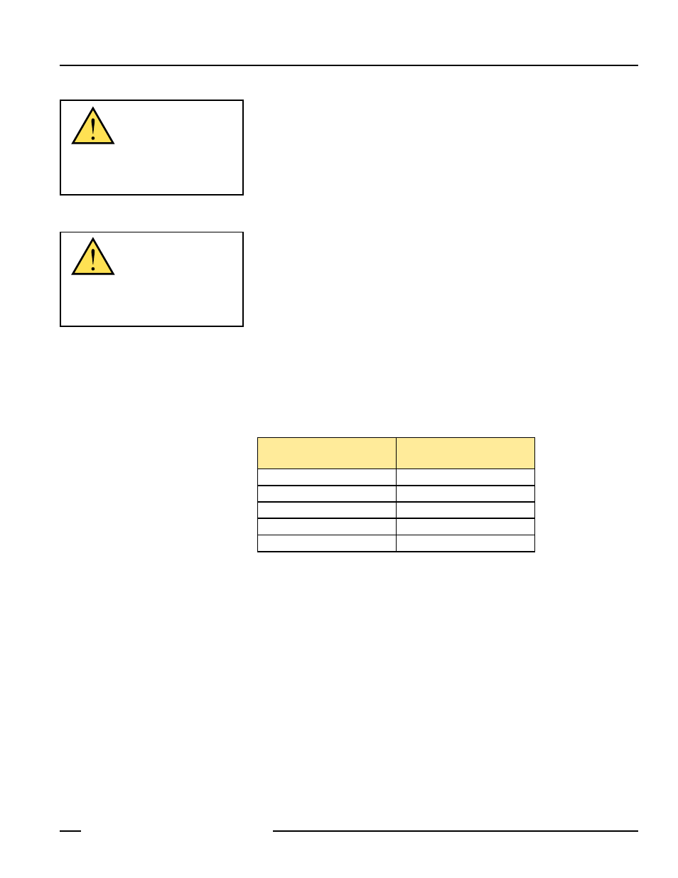
CAUTION . . .
Never stare directly into
the sensor lens. Laser light
can damage your eyes. Avoid placing any
mirror-like object in the beam. Never use a
mirror as a retroreflective target.
CAUTION . . .
This sensor contains
no user-servicable
components. Do not attempt to repair.
Incorrect component values may produce
hazardous laser radiation levels.
Figure 3. Minimum object detection size vs. distance from sensor
Distance from Sensor
to Object
Minimum Object
Detection Size
0.3 m (1')
2.5 mm (0.10")
1.5 m (5')
3.0 mm (0.12")
3 m (10')
4.5 mm (0.18")
15 m (50')
19 mm (0.75")
30 m (100')
25 mm (1.0")