Q45bb6ll series – laser retroreflective sensors, Overview, Alignment – Banner Q45 Laser DC Series User Manual
Page 2
Q45BB6LL Series – Laser Retroreflective Sensors
P/N 38244 rev. B
Banner Engineering Corp. • Minneapolis, MN U.S.A.
www.bannerengineering.com • Tel: 763.544.3164
Sensing Distance = X
Ø = Misalignment Angle
Y = X(tan Ø)
Y
CL
Overview
Status indicator LEDs for Power, Signal and Output are clearly visible beneath a raised
dome in the sensor’s transparent o-ring-sealed polycarbonate cover. The Power indicator
lights whenever power is applied to the sensor. The Signal LED lights whenever the
sensor sees its modulated light source, and pulses at a rate proportional to the strength
of the received light signal; this is the AID™ Alignment Indicating Device. The Output
indicator lights whenever the sensor’s output is conducting. This indicator is especially
useful when a timing logic module is used and Signal and Output conditions are not
concurrent.
Also located beneath the sensor’s o-ring-sealed cover are controls for light/dark operate
selection and Sensitivity (gain) adjustment.
Alignment
Conventional retroreflective photoelectric sensors are extremely easy to align. Beam
angles are wide, and retro targets are forgiving to angle of incidence of the light
beam. The beam of the Q45 laser sensor is very narrow, compared with the beam of
most retro sensors. As Figure 2 indicates, the effect of angular misalignment can be
dramatic. Alignment is critical because the beam may miss the retroreflective target
unless the retro target is large.
For example, with one BRT-2x2 mounted at a distance of 6 m (20') from the sensor,
one degree of angular misalignment will cause the center of the laser beam to miss
the center of the target by 4 inches (i.e., the beam will miss the edge of the reflector by
almost 3 inches).
Figure . Beam displacement per degree of misalignment
Sensor-to-Target
Distance (X)
Beam Displacement (Y)
for 1° of Misalignment
1.5 m (5')
25 mm (1")
3 m (10')
50 mm (2")
6 m (20')
100 mm (4")
15 m (50')
250 mm (10")
30 m (100')
500 mm (20")
45 m (150')
750 mm (30")
60 m (200')
1000 mm (40")
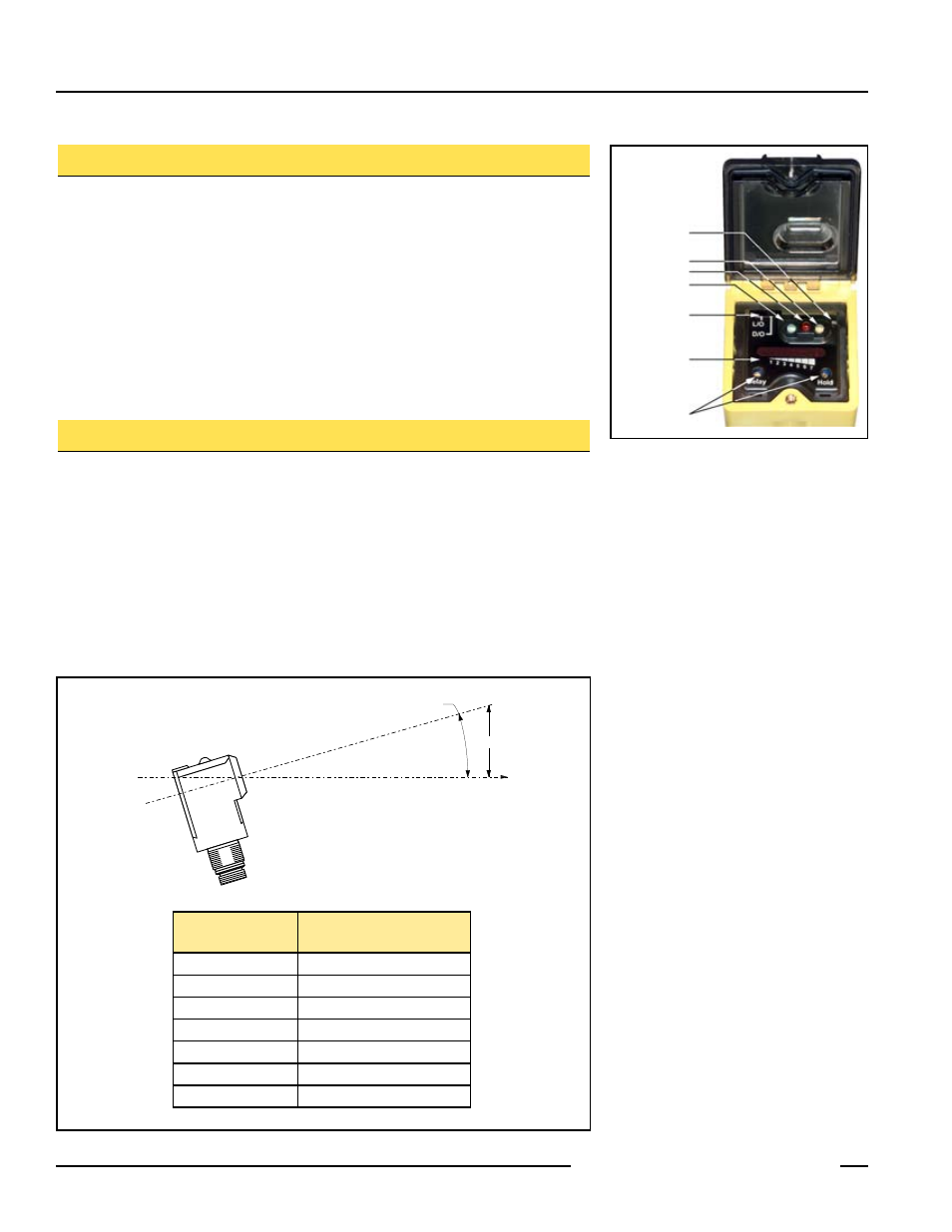
Figure 1. Sensor indicators and controls
Sensitivity
Adjustment
Optional Timing
Adjustments
Output Status
Indicator
Signal Indicator
Power ON
Indicator
Light/Dark
Operate Switch
Optional LED
Signal Strength
Display