Valu-beam 912 series sensors, Hookup diagrams for dc sm912 series sensors, Hookup to dc relay or solenoid – Banner VALU-BEAM Series User Manual
Page 8: Hookup to a logic gate hookup to micro-amp logic, Hookup to b series logic, Hookup to maxi-amp logic module emitter hookup, Hookup to programmable controller, Using sinking output), Using sourcing output), Mps-15 chassis)
BROWN
+10 - 30V dc
BLACK
BLACK wire
is not used
BLUE
(common)
WHITE
(sinking output)
1
2
3
4
5
6
7
8
dc+
dc com
I
N
P
U
T
S
P
r
o
g.
C
t
r
l.
Hookup shown is
typical for all inputs
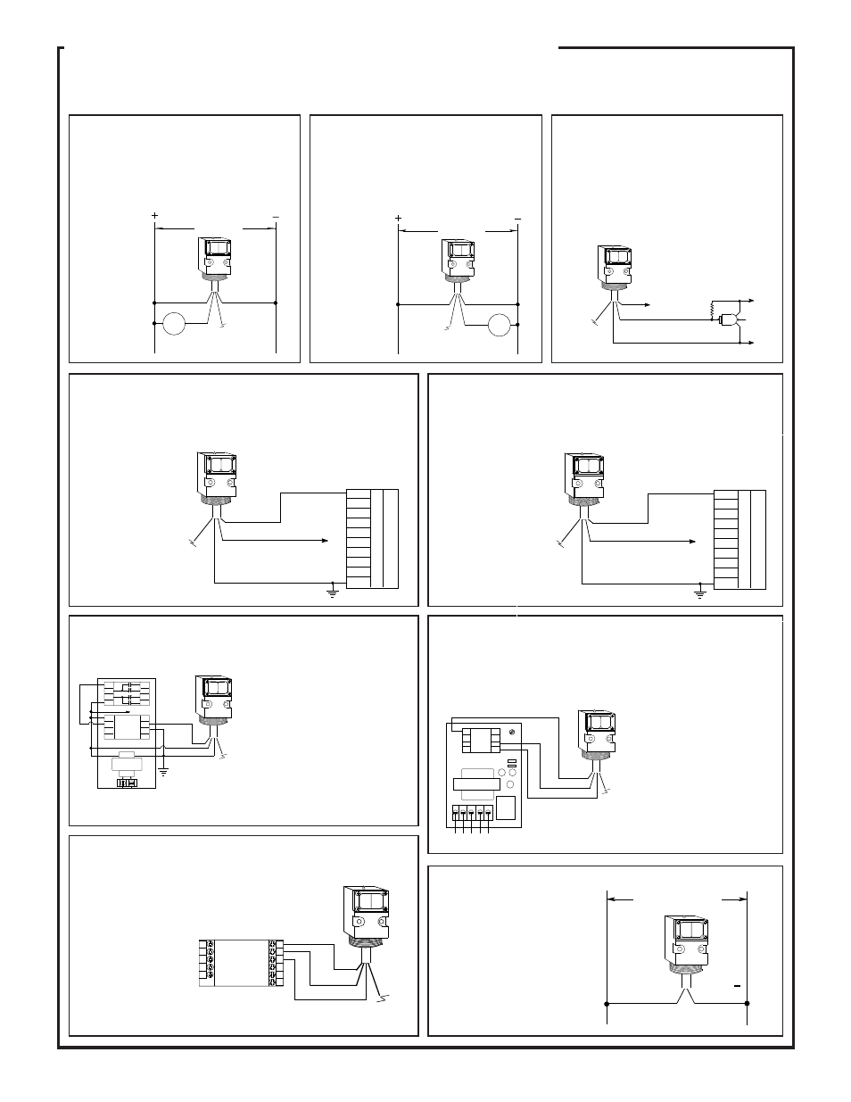
Hookup Diagrams for dc SM912 Series Sensors
Hookup to dc Relay or
Solenoid
(using sinking output)
Hookup to dc Relay or
Solenoid
(using sourcing output)
The diagram below shows hookup of a dc VALU-
BEAM to a dc load using the sensor's sinking
output, which is rated at 250mA maximum.
The BLACK
wire is not
used.
The diagram below shows hookup of a dc VALU-
BEAM to a dc load using the sensor's sourcing
output, which is rated at 250mA maximum.
The WHITE
wire is not
used.
The diagram below shows hookup of a dc VALU-
BEAM to a logic gate. A logic zero (0 volts dc)
is applied to the gate input when the VALU-
BEAM output is energized. When de-energized,
a logic one is applied. The logic supply negative
must be common to the VALU-BEAM supply
negative.
Hookup to a Logic Gate
Hookup to MICRO-AMP Logic
(MPS-15 chassis)
Hookup to B Series Logic
(MRB chassis)
The current sinking output (white
wire) of the VALU-BEAM is shown
connected to the input (pin 5) of a B
Series module. It may be connected
to the auxiliary input (pin 3) if de-
sired. (See description of module
for function of aux. input). Any B
Series module may be used. Ban-
ner PLUG LOGIC modules may
also be used (contact the factory for
further information).
The current sinking output(s) of VALU-BEAM sen-
sors may be connected directly to the input of CL Series
MAXI-AMP modules. A MAXI-AMP which is pow-
ered by ac voltage offers a dc supply with the capacity
to power one VALU-
BEAM sensor (see
hookup diagram).
When emitter/receiver
pairs are used, the
emitter should be pow-
ered from a separate
power source.
Hookup to MAXI-AMP Logic Module
Emitter Hookup
(ac or dc power)
Hookup to Programmable Controller
(sinking output)
This diagram shows hookup of a dc VALU-BEAM to a programmable
controller requiring a current sink, using the sensor's sinking output. The
BLACK wire
is not used.
Hookup to Programmable Controller
(sourcing output)
This diagram shows hookup of a dc VALU-BEAM to a programmable
controller requiring a current source, using the sensor's sourcing output. The
WHITE wire is not used.
BLACK
BLACK
wire
is not used
(-) dc
BLUE
(common)
* Use pullup resistor to
logic supply
+5V to 30V dc
logic supply
*
BROWN
+10 -30V dc
WHITE (sinking)
output, 150mA max.
Hookup shown is
typical for all
inputs.
Hookup shown is
typical for all
inputs.
The current sinking (white) output of the VALU-BEAM is shown con-
nected to the primary input (pin 7) of a MICRO-AMP logic module. It may
be connected, instead, to the other inputs (see logic module descriptions in
the Banner product catalog). The following logic modules may be used:
BLUE
Micro-
Amp
Logic
BLACK wire
is not used
Relay
120
Vac
N
O
C
N
C
MODEL MPS-15
WHITE
BROWN
7
8
1
2
6
5
4
3
NO
NC
BLACK
MA4-2
One-shot
MA5
On/off delay
MA4G
4-input "AND"
MA4L
Latch
L1
L2
10 to 250V ac or V dc
SMA91E
SMA91EF
SMA91ESR
+
Brown
Blue
BLACK
(sourcing
output)
WHITE
BROWN
+10 - 30V dc
White wire
is not used
BLUE
(common)
1
2
3
4
5
6
7
8
dc+
dc com
I
N
P
U
T
S
P
r
o
g.
C
t
r
l.
Hookup shown is
typical for all inputs
BLACK wire
is not used
WHITE
BROWN
BLUE
+15V dc
120 Vac
B Series
Module
MRB
7
8
1
2
3
4
5
6
7
8
1
2
3
4
5
6
BLACK
BLACK wire
is not used
WHITE
BROWN
CL3RA
CL3RB
CL5RA
CL5RB
8
7
6
5
4
9
10
11
1
2
3
BLUE
BLACK
WHITE
BROWN
BLUE
BLACK
10 - 30V dc
LOAD
WHITE
BROWN
BLUE
BLACK
10 - 30V dc
LOAD
VALU-BEAM 912 Series Sensors
8
NOTE: each output has a maxi-
mum load capacity of 250mA.
For emitter hookup, see below.