Valu-beam 915 series sensors, Beam pattern sensing mode, Models excess gain – Banner VALU-BEAM Series User Manual
Page 13: Smw915fp, Sma915fp, Smb915fp, Smw915f, Sma915f, Smb915f, Environmental factors for plastic fiber optics
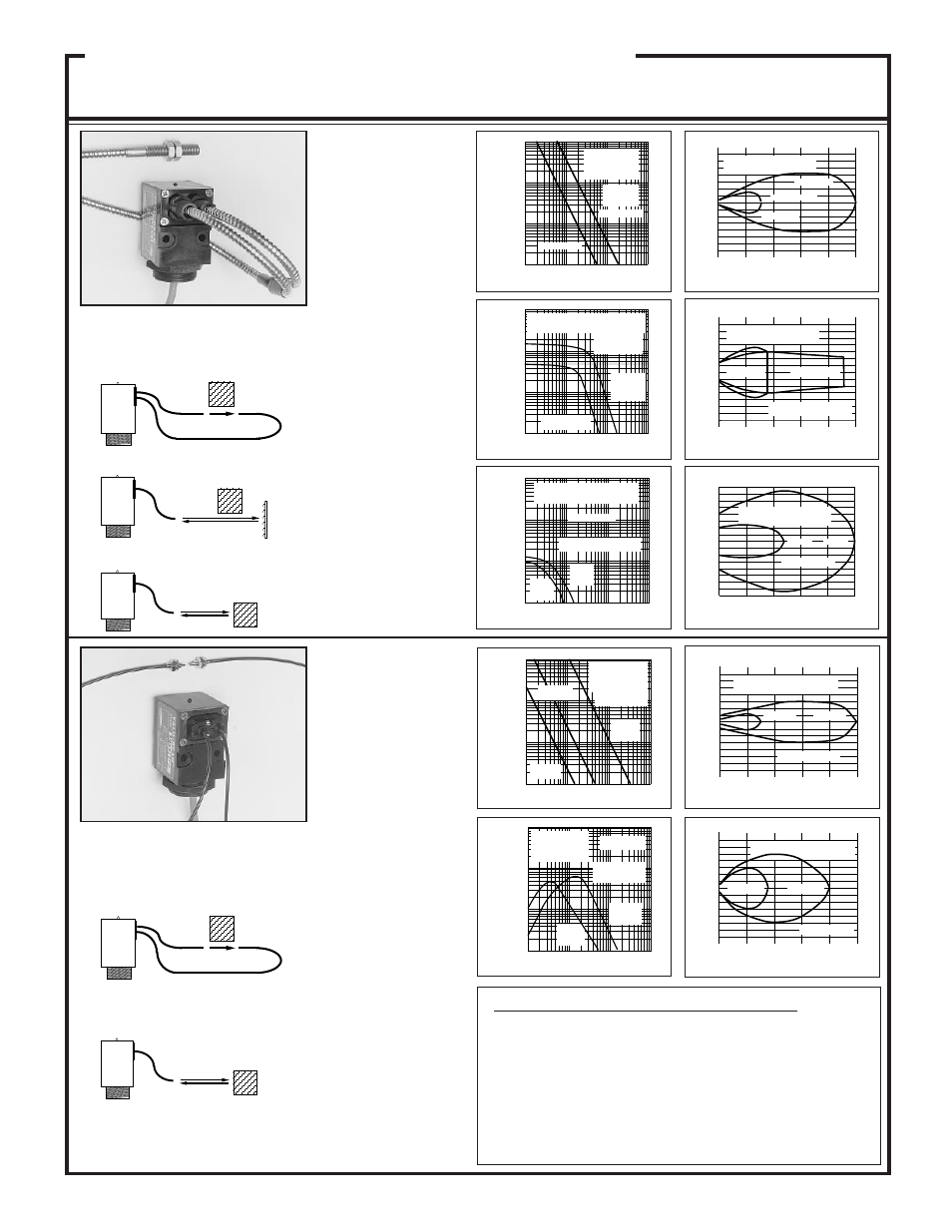
Beam Pattern
Sensing Mode
The powerful modulated vis-
ible beam of these sensors
makes them compatible with
all Banner plastic fiber optic
assemblies, and their fiber
fittings will accomodate both
terminated and unterminated
type assemblies. Plastic fi-
bers are ideal for short-range
sensing where the environ-
ment is not severe. Plastic
fiber optic model information
may be found in the Banner
product catalog
These sensors will also inter-
face with Banner glass fiber
optic assemblies.
FIBER OPTIC Mode
(plastic fibers)
FIBER OPTIC Mode
(glass fibers)
SMW915FP
Voltage: 12 to 28V ac/dc
SMA915FP
Voltage: 90 to 130V ac
SMB915FP
Voltage: 210 to 250V ac
Range: see E.G. curves
Response: 20ms on/off
Beam: visible red, 650nm
VALU-BEAM 915 Series Sensors
10
1
DISTANCE
100
1000
.1 IN
1 IN
10 IN
100 IN
IT23S fibers
IT13S fibers
Opposed
mode,
glass fibers
SMW915F,
SMA915F,
SMB915F
E
X
C
E
S
S
G
A
I
N
I
1000
100
10
1
.1 FT
1 FT
10 FT
100 FT
DISTANCE
with L9 lens and
BT13S fibers
with L16F
lens
and BT13S
fibers
SMW915F, SMA915F,
SMB915F
Retroreflective
mode,
w/BRT-3
3" target
E
X
C
E
S
S
G
A
I
N
I
1000
100
10
1
.1 IN
1 IN
10 IN
100 IN
with
BT13S
fibers
with
BT23S
fibers
DISTANCE
Range based on 90%
reflectance white test card
Diffuse mode
SMW915F, SMA915F,
SMB915F
E
X
C
E
S
S
G
A
I
N
I
1
10
100
1000
.1 IN
1 IN
10 IN
100 IN
PIT46U
with L2
lenses
PIT26U,
no lens
DISTANCE
Opposed mode,
plastic fibers
PIT46U,
no lenses
SMW915FP,
SMA915FP,
SMB915FP
E
X
C
E
S
S
G
A
I
N
I
1
10
100
1000
.01 IN
.1 IN
1 IN
10 IN
with
PBT46U
fiber
with
PBT26U
fiber
DISTANCE
SMW915FP,
SMA915FP,
SMB915FP
Range based on
90% reflectance
white test card
Diffuse mode,
plastic fibers
E
X
C
E
S
S
G
A
I
N
I
4
8
12
16
20
0
0
1
2
3
1
2
3
I
N
C
H
E
S
OPPOSED DISTANCE --INCHES
IT23S fibers
IT13S fibers
opposed mode
SMW915F, SMA915F,
SMB915F
.3
.6
0
0
.025
1.2
1.5
.050
.075
.1
.025
.050
.075
.1
.9
BT23S
BT13S
Diffuse mode
I
N
C
H
E
S
DISTANCE TO 90% WHITE TEST CARD--INCHES
SMW915F, SMA915F,
SMB915F
4
8
12
16
20
0
0
2
4
6
2
4
6
w/L9 lens
w/L16F lens
I
N
C
H
E
S
DISTANCE TO REFLECTOR--FEET
BT13S fiber, retroreflective
mode, with BRT-3 reflector
SMW915F, SMA915F,
SMB915F
1
2
3
0
4
0
.6
5
1.2
1.8
.6
1.2
1.8
PIT26U
PIT46U
Opposed mode
I
N
C
H
E
S
OPPOSED DISTANCE--INCHES
SMW915FP, SMA915FP,
SMB915FP
.3
.6
0
0
.05
.10
.15
.05
.10
.15
1.2
1.5
.9
PBT26U
PBT46U
Diffuse mode
I
N
C
H
E
S
DISTANCE TO 90% WHITE TEST CARD--INCHES
SMW915FP, SMA915FP,
SMB915FP
Models
Excess Gain
Environmental Factors for Plastic Fiber Optics
OPERATING TEMPERATURE OF FIBER OPTIC ASSEMBLIES: -30 to
+70 degrees C (-20 to +158 degrees F).
CHEMICAL RESISTANCE OF FIBER OPTIC ASSEMBLIES: the acrylic
core of the monofilament optical fiber will be damaged by contact with acids,
strong bases (alkalis), and solvents. The polyethylene jacket will protect the
optical fiber from most chemical environments; however, materials may
migrate throught the jacket with long-term exposure. Samples of plastic fiber
optic material are available from Banner for testing and evaluation.
SMW915F
Voltage: 12 to 28V ac/dc
SMA915F
Voltage: 90 to 130V ac
SMB915F
Voltage: 210 to 250V ac
Range: see E.G. curves
Response: 20ms on/off
Beam: infrared, 880nm
OPPOSED
OBJECT
OBJECT
RETROREFLECTIVE TARGET
RETRO
DIFFUSE
OBJECT
OBJECT
DIFFUSE
OPPOSED
OBJECT
13
Fiber optic sensing is often
the answer when, due to space
or environmental limitations,
the sensor itself cannot be
placed at the actual sensing
position. These sensors' pow-
erful modulated infrared
beam is compatible with all
Banner glass fiber optics in
the opposed, retroreflective,
and diffuse sensing modes.
Banner glass fiber optic se-
lection information may be
found in the product catalog.
Sensor/fiber interface is wa-
terproof to maintain complete
sensing system moisture re-
jection.