Valu-beam 912 series sensors, Beam pattern models excess gain sensing mode, Fiber optic mode – Banner VALU-BEAM Series User Manual
Page 7: Opposed fiber optic mode (glass fibers), Sma91ef & sm91rf, Sm912f, Sm2a912f
7
VALU-BEAM 912 Series Sensors
Beam Pattern
Models
Excess Gain
Sensing Mode
1000
100
10
1
with
IT23S
fibers
with
IT23S &
L16F
lenses
DISTANCE
SMA91EF &
SM91RF,
SMA91EF &
SM2A91RF
.1 FT
1 FT
10 FT
100 FT
with
IT23S
and
L9
lenses
with
IT13S
fibers
E
X
C
E
S
S
G
A
I
N
I
8
16
24
32
40
0
0
4
8
12
4
8
12
I
N
C
H
E
S
OPPOSED DISTANCE--FEET
SMA91EF/SM91RF,
SMA91EF/SM2A91RF
IT23S fibers
with L16F lenses
IT23S fibers
with L9 lenses
SMA91EF &
SM91RF
Voltage: 10 to 30V dc
("EF": 10-250V ac/dc)
Range: see E.G. curves
Response: 8ms on/4 off
Beam: infrared, 880nm
SMA91EF &
SM2A91RF
Voltage: 24 to 250V ac
("EF": 10-250V ac/dc)
Range: see E.G. curves
Response: 8ms on/4 off
Beam: infrared, 880nm
Repeatability:
1.0ms (all models)
SM912F
Voltage: 10 to 30V dc
Range: see E.G. curves
Response: 4ms on/off
Beam: infrared, 880nm
FIBER OPTIC Mode
RETRO
DIFFUSE
SM2A912F
Voltage: 24 to 250V ac
Range: see E.G. curves
Response: 8ms on/off
Beam: infrared, 880nm
10
1
DISTANCE
100
1000
.1 IN
1 IN
10 IN
100 IN
IT23S fibers
IT13S fibers
Opposed
mode,
glass fibers
SM912F, SM2A912F
E
X
C
E
S
S
G
A
I
N
I
1000
100
10
1
.1 IN
1 IN
10 IN
100 IN
with
BT13S
fibers
with
BT23S
fibers
DISTANCE
Range based on 90%
reflectance white test card
Diffuse mode
SM912F,
SM2A912F
E
X
C
E
S
S
G
A
I
N
I
1000
100
10
1
.1 FT
1 FT
10 FT
100 FT
DISTANCE
with L9 lens
and BT13S
fibers
with L16F lens
and BT13S
fibers
Retroreflective
mode, w/BRT-3 3"
target
SM912F, SM2A912F
E
X
C
E
S
S
G
A
I
N
I
4
8
12
16
20
0
0
1
2
3
1
2
3
I
N
C
H
E
S
IT23S fibers
IT13S fibers
opposed mode
SM912F, SM2A912F
OPPOSED DISTANCE --INCHES
0
Retroreflective mode,
BT13S fiber, BRT-3 reflector
with L9 lens
with L16F lens
4
8
12
16
20
0
2
4
6
2
4
6
I
N
C
H
E
S
DISTANCE TO REFLECTOR--FEET
SM912F, SM2A912F
.3
.6
0
0
.025
1.2
1.5
.050
.075
.1
.025
.050
.075
.1
.9
BT23S
BT13S
Diffuse mode
I
N
C
H
E
S
DISTANCE TO 90% WHITE TEST CARD--INCHES
SM912F, SM2A912F
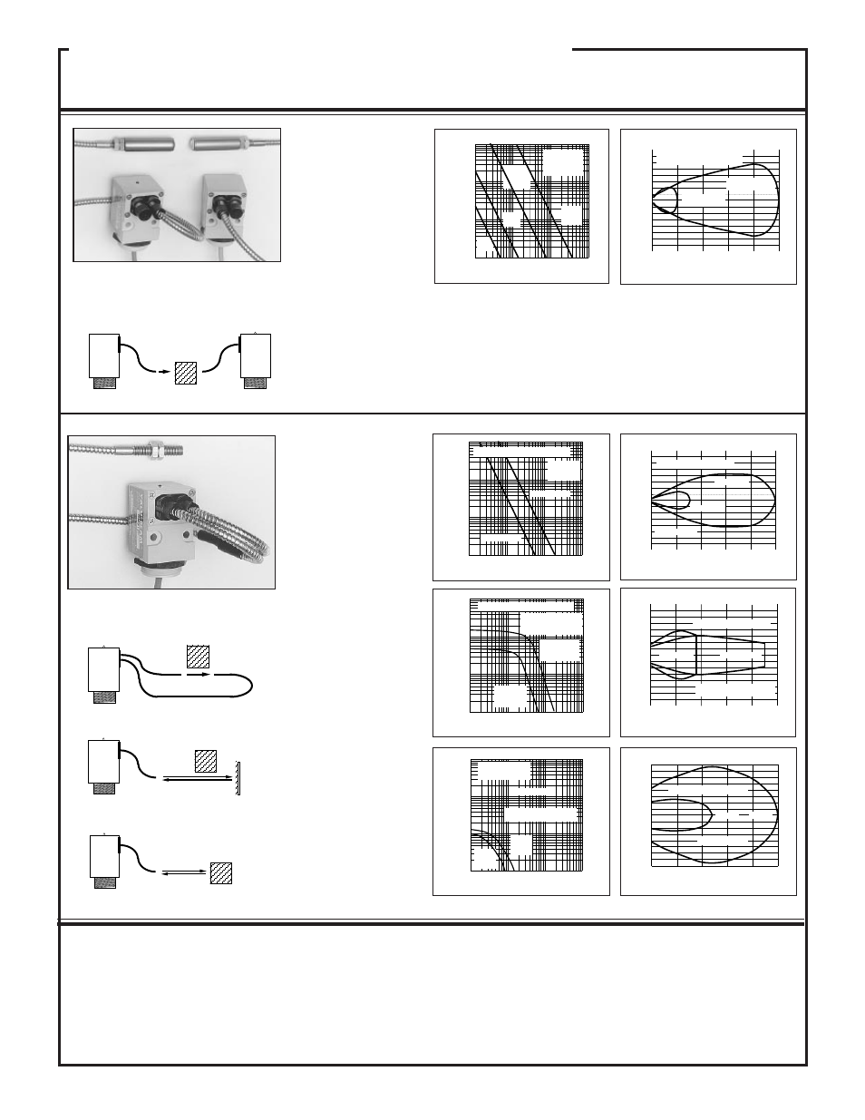
Fiber optic sensing is often
the answer when, due to space
or environmental limitations,
the sensor itself cannot be
placed at the actual sensing
position. These sensors' pow-
erful modulated infrared
beam is compatible with all
Banner glass fiber optics in
the opposed, retroreflective,
and diffuse sensing modes
(see Banner product catalog).
Sensor/fiber interface is wa-
terproof to maintain complete
sensing system moisture re-
jection.
Repeatability:
1.3ms (dc models);
2.6ms (ac models)
OPPOSED
OBJECT
OBJECT
OBJECT
RETROREFLECTIVE TARGET
OBJECT
EMITTER
RECEIVER
OPPOSED FIBER OPTIC
MODE (glass fibers)
These opposed mode fiber optic emitter-receiver pairs are used where the
separation between emitting and receiving fibers is greater than a few feet, or
where it is inconvenient to run both fibers from a single VALU-BEAM sensor.
These models have a watertight o-ring sealed sensor/fiber interface, and are
compatible with all Banner glass fiber optic assemblies (see product catalog).