Remote programming, Figure 6. quick disconnect models, Figure 7. din rail mounting – Banner D11 Series User Manual
Page 6: Figure 8. mounting bracket
3. Slide the fiber gripper back down to lock.
A fiber adaptor is included for use with 0.25 mm (0.01") or 0.5 mm (0.02") diameter fibers.
Programming
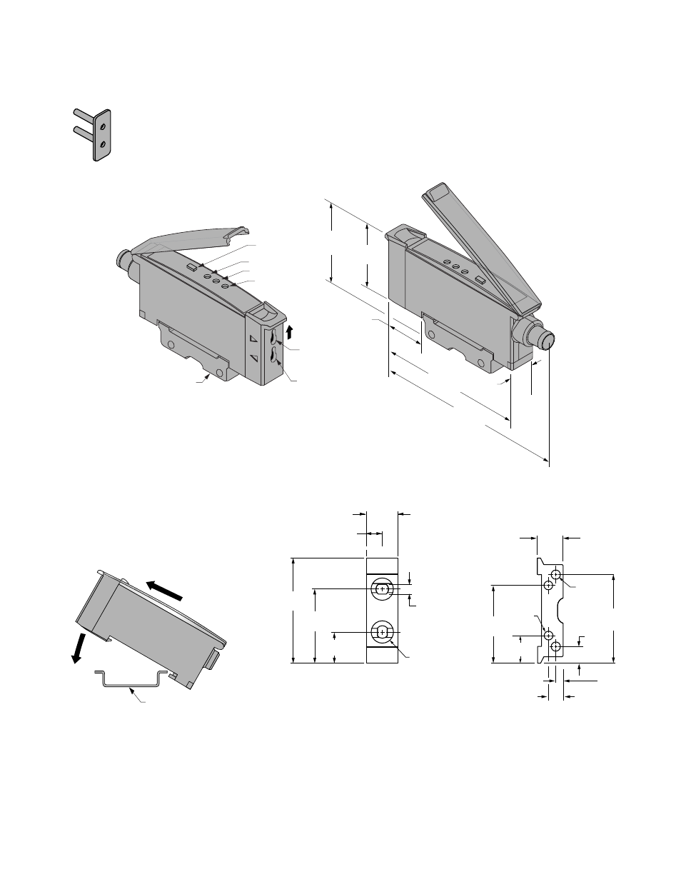
Push Button
Power Indicator
Output Indicator
Signal Strength Indicator
ø 1.0 mm (0.04")
Plastic Fiber Emitter Port
ø 1.0 mm (0.04")
Plastic Fiber Receiver Port
Mounting Bracket
(Included)
35.0 mm
(1.38")
17.6 mm
(0.69")
64.1 mm
(2.53")
79.0 mm
(3.11")
11.0 mm
(0.43")
29.0 mm
(1.14")
Slide Up
to Release
Fibers
Figure 6. Quick Disconnect Models
DIN Rail
Figure 7. DIN Rail Mounting
35.0 mm
(1.38")
25.1 mm
(0.99")
30.2 mm
(1.19")
5.0 mm
(0.20")
9.9 mm
(0.39")
2 x C’sink
ø 7.9 mm (0.31")
3.2 mm (0.13") deep
ø4.4 (0.18") thru
2 x ø 3.25 mm
(0.128")
2 x 3.5 mm
(0.14")
5.5 mm
(0.22")
11.0 mm
(0.44")
25.6 mm
(1.01")
9.6 mm
(0.38")
2.5 mm
(0.10")
8.6 mm
(0.34")
4.8 mm
(0.19")
2 x ø 3.18 mm
(0.125")
Figure 8. Mounting Bracket
Remote Programming
Connect the D11 Expert's white wire to a remote switch for three sensor programming functions:
1. Disable or enable the push button
2. TEACH mode programming of sensitivity
D11 Expert Series
6
www.bannerengineering.com - tel: 763-544-3164
P/N 44279 Rev. C