Run mode – Banner D11 Series User Manual
Page 2
Supply Protection Circuitry
Protected against reverse polarity and transient voltag-
es
Output Configuration
One (SPST) NPN (sinking) or PNP (sourcing) open-
collector transistor, depending on model; programma-
ble for light or dark operate
Output Rating
150 mA maximum
Off-state leakage current: <5 microamps at 30V dc
On-state saturation voltage: <1V at 10 mA dc; <1.5V at
150 mA dc
Output Protection Circuitry
Protected against false pulse on power-up and continu-
ous overload or short-circuit
Output Response Time
200 microseconds (0.2 milliseconds) ON and OFF (40
milliseconds OFF when pulse stretcher is program-
med). NOTE: 100 millisecond delay on power-up; out-
put is non-conducting during this time
Output Timing Functions
ON/OFF (no delay) or fixed 40 millisecond OFF-delay
pulse stretcher; selected by push button
Operating Temperature
–10 to +55 ºC (–14 to +131 ºF)
Maximum relative humidity 90% at 50ºC (non-condens-
ing)
Certifications
Sensing Beam
Visible red, 680 nm
Repeatability
66 microseconds
Adjustments
Push button TEACH mode sensitivity setting (see
TEACH mode, page 2); remote TEACH mode input is
provided
Indicators
Three LEDs: Green, Yellow and Red
Green LED lights for dc power ON and flashes when
ready to register sensing condition during TEACH
mode: 1 Hz when waiting to learn first sensing condi-
tion; 2 Hz when waiting to learn second sensing condi-
tion; 4 Hz when output is overloaded.
Yellow LED lights for output ON (conducting).
Red LED is Banner’s patented Alignment Indicating
Device (AID™, U.S. patent #4356393) which lights
whenever the sensor “sees” a light condition and su-
perimposes a pulse rate which is proportional to the
strength of the received light signal (the stronger the
signal, the faster the pulse rate).
Construction
Black ABS flame retardant housing with acrylic cover
Stainless steel M3 x 0.5 hardware for use with ABS
mounting bracket (supplied)
Environmental Rating
IEC IP54; NEMA 2
Connections
2 m (6.5 ft) or 9 m (30 ft) attached cable, or 4-pin Pico-
style quick-disconnect fitting; Cables for QD models
are purchased separately
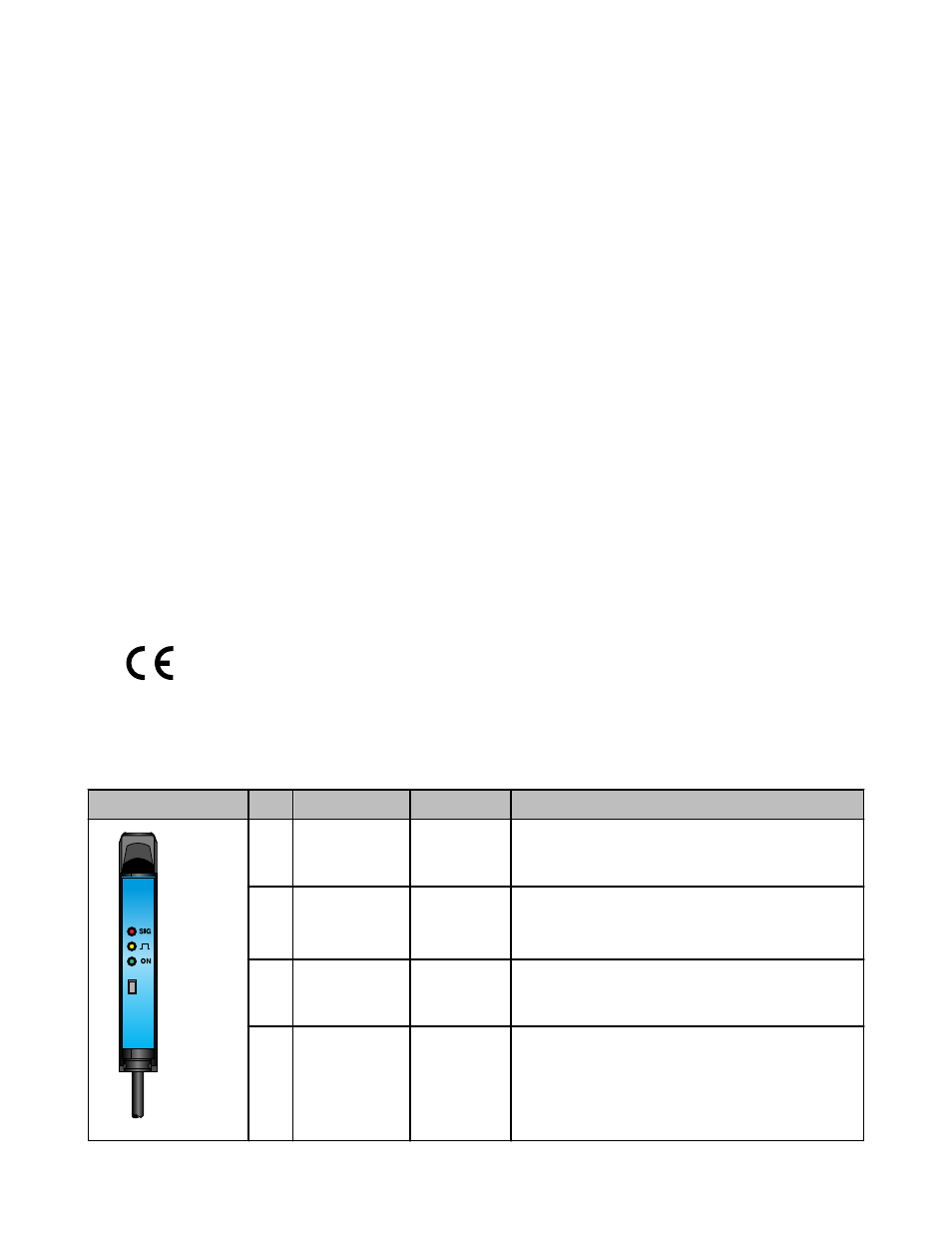
Run Mode
Run mode is the normal operation of the D11 Expert series. The LED indicators operate in Run mode, as follows:
Indicator
LED Color
Function
1
2
3
4
1
Signal Strength
(SIG)
Red
Lights when the sensor "sees" its modulated light source
and pulses at a rate proportional to the received light signal
strength.
2
Output
Amber
Follows the action of the output:
• On when the output is energized
• Off when the output is de-energized
3
Power ON
Green
Solid when power is applied.
Flashes at approximately 4 Hz to indicate the output is over-
loaded
4
Button
n/a
Programming push button
D11 Expert Series
2
www.bannerengineering.com - tel: 763-544-3164
P/N 44279 Rev. C