U-gage, Analog q45ur remote ultrasonic sensors, Remote window limit programming – Banner U-GAGE Q45UR Series—Analog User Manual
Page 6: Analog q45ur series response curves
U-GAGE
™
Analog Q45UR Remote Ultrasonic Sensors
6
P/N 59323 Rev. C
Banner Engineering Corp.
•
Minneapolis, MN U.S.A.
www.bannerengineering.com • Tel: 763.544.3164
Step 1
Access Limit
Programming Mode
Step 2
Set First Limit
(Near or Far)
Step 3
Set Second Limit
(Far or Near)
T
T >2 sec
Wait >0.8 seconds
before next input
+5 to 24V dc
<2V dc
(or open circuit)
T
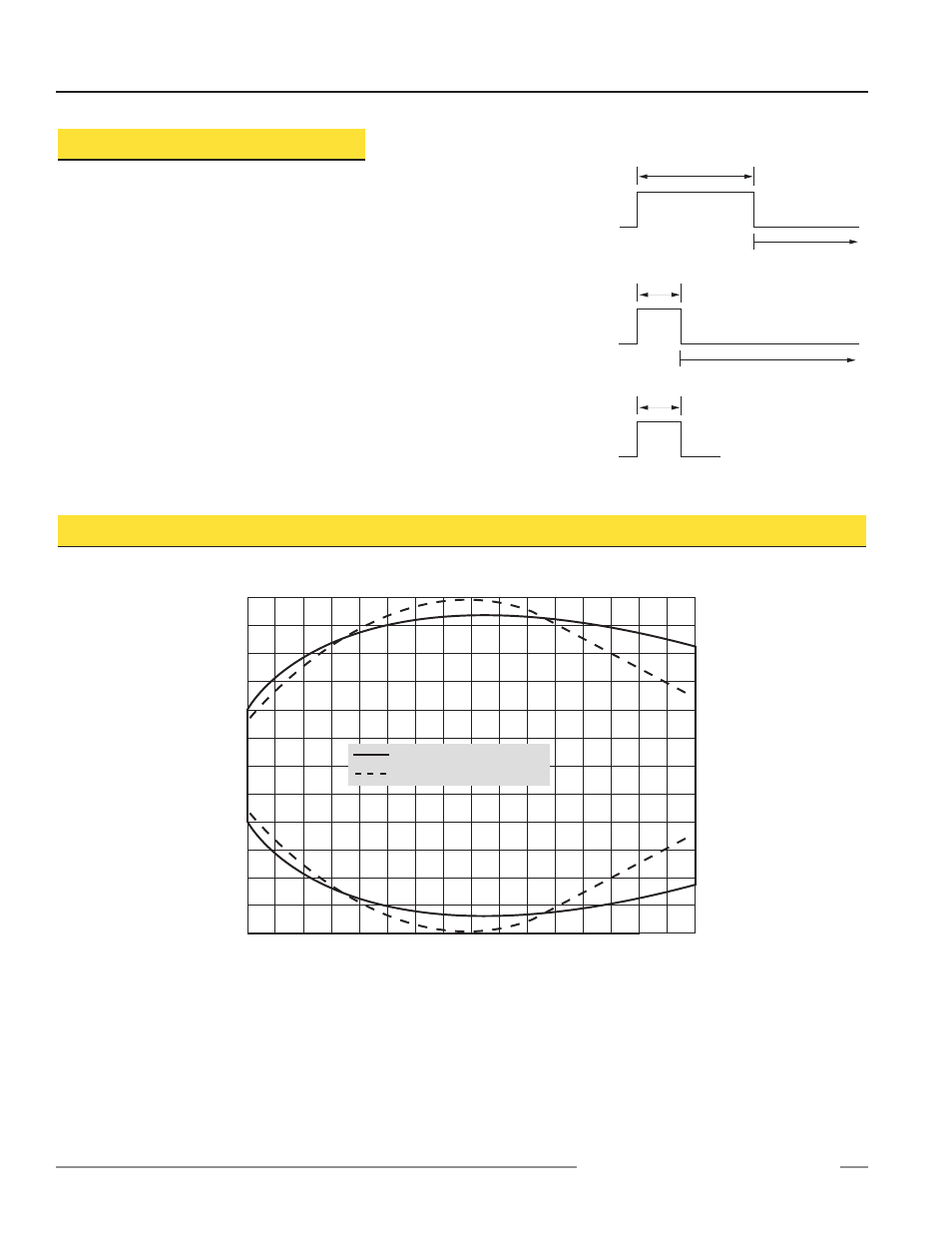
0.04 sec Wait >2 seconds before next input +5 to 24V dc <2V dc (or open circuit) T 0.04 sec +5 to 24V dc <2V dc (or open circuit) Remote Window Limit Programming The yellow wire of the Analog Q45UR may be connected to a A remote programming input is generated when +5 to 24V NOTES: programming. (The remote programming input is 2) Also see the notes regarding window limit programming on page 4. Analog Q45UR Series Response Curves Lateral Distance Target Distance -0.08" -0.16" -0.24" -0.32" -0.40" 0.08" 0.16" 0.24" 0.32" 0.40" -2.0 mm -4.0 mm -6.0 mm -8.0 mm -10.0 mm 2.0 mm 0 0 4.0 mm 6.0 mm 8.0 mm 10.0 mm 0.47" 12.0 mm -0.47" -12.0 mm 50 mm 2.0" 75 mm 3.0" 100 mm 4.0" 125 mm 5.0" 150 mm 6.0" 175 mm 7.0" 200 mm 8.0" 225 mm 9.0" 250 mm 10.0" 50 mm x 50 mm Alum. Plate 10 mm Dia. Alum. Rod NOTE: The pattern displayed for the 50 mm x 50 mm Aluminum plate is referenced to the EDGE of the plate. The pattern displayed for the 10 mm dia. Aluminum rod is referenced to the CENTER of the rod. D
switch or process controller for remote programming of the
sensing window limits. The programming procedure is the
same as for the push button (see page 4).
dc is applied to the yellow wire. The timing diagrams, right,
define the required input pulses.
1) The push button is disabled during remote limit
disabled during push button programming.)