Programming modes, Teach mode, Sensor output configuration mode – Banner D12 Series User Manual
Page 2
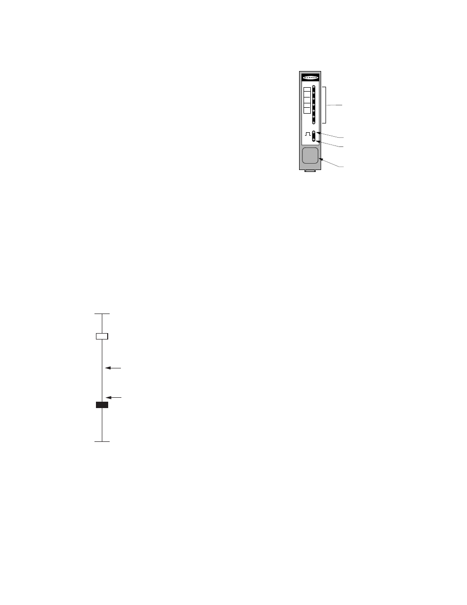
an advanced and comprehensive LED status display, plus sensor self-diagnostics and an alarm output to signal marginal sensing condi-
tions.
Unlike competitive sensors, D12 Expert models have no exposed switches or ad-
justments. All programming is accomplished using a single, sealed push button,
using quick commands. Your settings remain secure, and the sensor is sealed
against the elements of the sensing environment. Also, a separate input is provi-
ded for remote programming (see
Models are available for either glass or plastic fiber optics. Fiber optics are pur-
chased separately to fit your exact sensing application. A few representative fiber
optic styles are listed, see
on page 9 . See Banner's product cat-
alog for the full selection of fiber optic assemblies.
ON
7
6
5
4
3
2
1
ALM
LO
DO
40 ms
0 ms
7-Segment bar graph indicates:
• Signal strength
• Sensing contrast
• Programming status
• Diagnostic display
Output indicator
Power ON indicator
Programming push button
Programming Modes
TEACH Mode
All photoelectric sensing applications (excluding analog response applications) involve differentiating between two received light levels.
The condition with the higher received light level is known as the light condition, and the condition with the lower received light level is
known as the dark condition. The difference between the two conditions is the sensing contrast.
The D12 Expert TEACH mode evaluates the light and dark sensing conditions and automatically adjusts the sensitivity to the optimal
level. Programming is fast, easy, and accurate.
D12 Expert sensors offer high excess gain needed for demanding sensing environments and/or for long-range sensing. However, unlike
standard D12 sensors, D12 Expert sensors also excel in low contrast sensing applications. When a D12 Expert sensor recognizes a low-
contrast application during the TEACH mode process, the sensor’s on-board microprocessor expands the bottom end of the sensitivity
range to establish an accurate setting that allows the sensor to respond to the slight difference in received light levels.
Max. Light Signal
D12E2 Threshold
(Excess gain = 1x)
Light Sensing
Condition
D12E Threshold
(Excess gain = 1x)
Min. Light Signal
Dark Sensing
Condition
D12E and D12E2 models set their sensing threshold points differently during the
TEACH mode process. D12E sensors automatically place the switching threshold just
above the dark condition taught to the sensor. This scheme works exceptionally well
for sensing a very small sensing contrast, where the light level represented by the
dark condition remains constant. However, in some applications, a subtle rise in the
amount of light received in the dark condition may prevent the D12E from responding
to the intended sensing event.
D12E2 models automatically set the switching threshold at the mid-point between the
light and dark sensing conditions taught to the sensor. This mid-point switching thresh-
old allows D12E2 model sensors to ignore subtle changes in both the light and dark
sensing conditions. D12E2 models were first developed to ignore a small amount of
web flutter in high-speed registration color-mark-sensing applications.
At the end of the TEACH mode process, the D12 Expert bar graph indicator flashes
one to seven segments to indicate the relative sensing contrast (see
on page 6), so you know how forgiving your application will be to
changing sensing conditions.
Sensor Output Configuration Mode
The Output Configuration Program mode allows you to set the sensor’s output for either no delay or for a fixed 40 millisecond pulse
stretcher (OFF-delay) for use with loads (or circuit inputs) that are too slow to react to a quick event. With no OFF delay, sensing re-
sponse is a fast 200 microseconds (.0002 seconds) both ON and OFF.
The output can also be configured for either light operate (LO) or dark operate (DO). Light operate energizes the sensor’s load output
when the light condition is sensed, and dark operate energizes the load output for the dark condition.
The output configuration can be checked at any time by holding down the push button for 2 seconds. The sensor’s 7-segment LED
display indicates the current setting for 10 seconds (see
#unique_12/IMAGE_57D2F1371D264F82A6C66190AD29F294
on page 6),
while the sensor continues normal operation. Factory settings for the output configuration are no delay (0 ms) and light operate (LO).
D12 Expert Series - TEACH-Mode Fiber Optic Sensors
2
www.bannerengineering.com - tel: 763-544-3164
P/N 041974 Rev. D