Q45vr3 series, Q45vr3 series indicators and controls, Q45vr3 series hookups – Banner Q45 Series User Manual
Page 9: Quick-disconnect (qd) option
Q45VR3 Series
page
9
Banner Engineering Corp.
•
Minneapolis, U.S.A.
www.bannerengineering.com • Tel: 763.544.3164
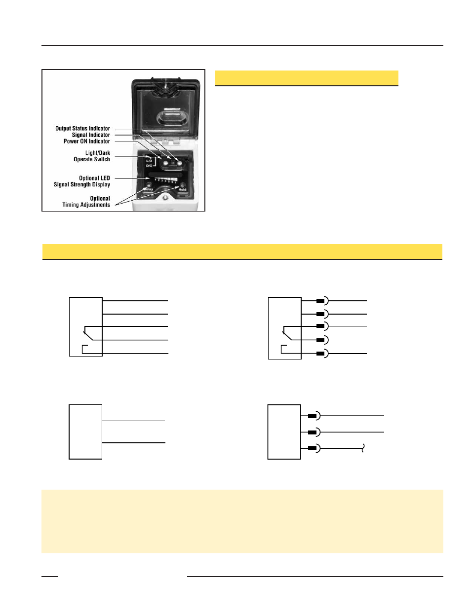
Q45VR3 Series Indicators and Controls
Status indicator LEDs for Power, Signal and Output are clearly visible
beneath a raised dome in the sensor’s transparent o-ring-sealed Lexan
®
cover. The Power indicator lights whenever power is applied to the sensor.
The Signal LED lights whenever the sensor sees its modulated light
source, and pulses at a rate proportional to the strength of the received
light signal; this is the AID™ Alignment Indicating Device*. The Output
indicator lights whenever the sensor’s output relay is energized. This indi-
cator is especially useful when a timing logic module is used and Signal
and Output conditions are not concurrent.
Also located beneath the sensor’s o-ring-sealed cover are controls for
light/dark operate selection and Sensitivity adjustment.
* US patent no. 4356393
Figure 1. Indicators and controls on the Q45VR3 Series
Sensors
Q45VR3 Sensors with Attached Cable
Q45VR3 Sensors with Quick-Disconnect
5-Pin Mini-Style ( model suffix Q)
Q453E Emitters with Attached Cable
Q453EQ Emitters with Quick-Disconnect
3-Pin Mini-Style
bu
ye
wh
NC
C
NO
bn
bk
24 - 250V ac or 12 - 250V dc*
NC
C
NO
bu
ye
wh
bn
bk
24 - 250V ac or 12 - 250V dc*
bn
bu
24-250V ac or 12-250V dc*
bn
bk
bu
24-250V ac or 12-250V dc*
Q45VR3 Series Hookups
*NOTE: Connection of dc power is without regard to polarity.
Quick-Disconnect (QD) Option
AC Q45VR3 Series sensors are sold with either a 2 m (6.5') or a 9 m (30') attached PVC-covered cable, or with a 3-pin Mini-
style (opposed mode emitter) or 5-pin Mini-style Quick-Disconnect (QD) cable fitting.
Mini-style QD sensors are identified by the suffix “Q” in their model number suffix. Mating cables for QD Q45VR3 sensors are
specified on page 10.