Front panel removal, Figure 18 removing front panel, Main printed circuit (pc) board removal – Bird Technologies 4391A User Manual
Page 35
23
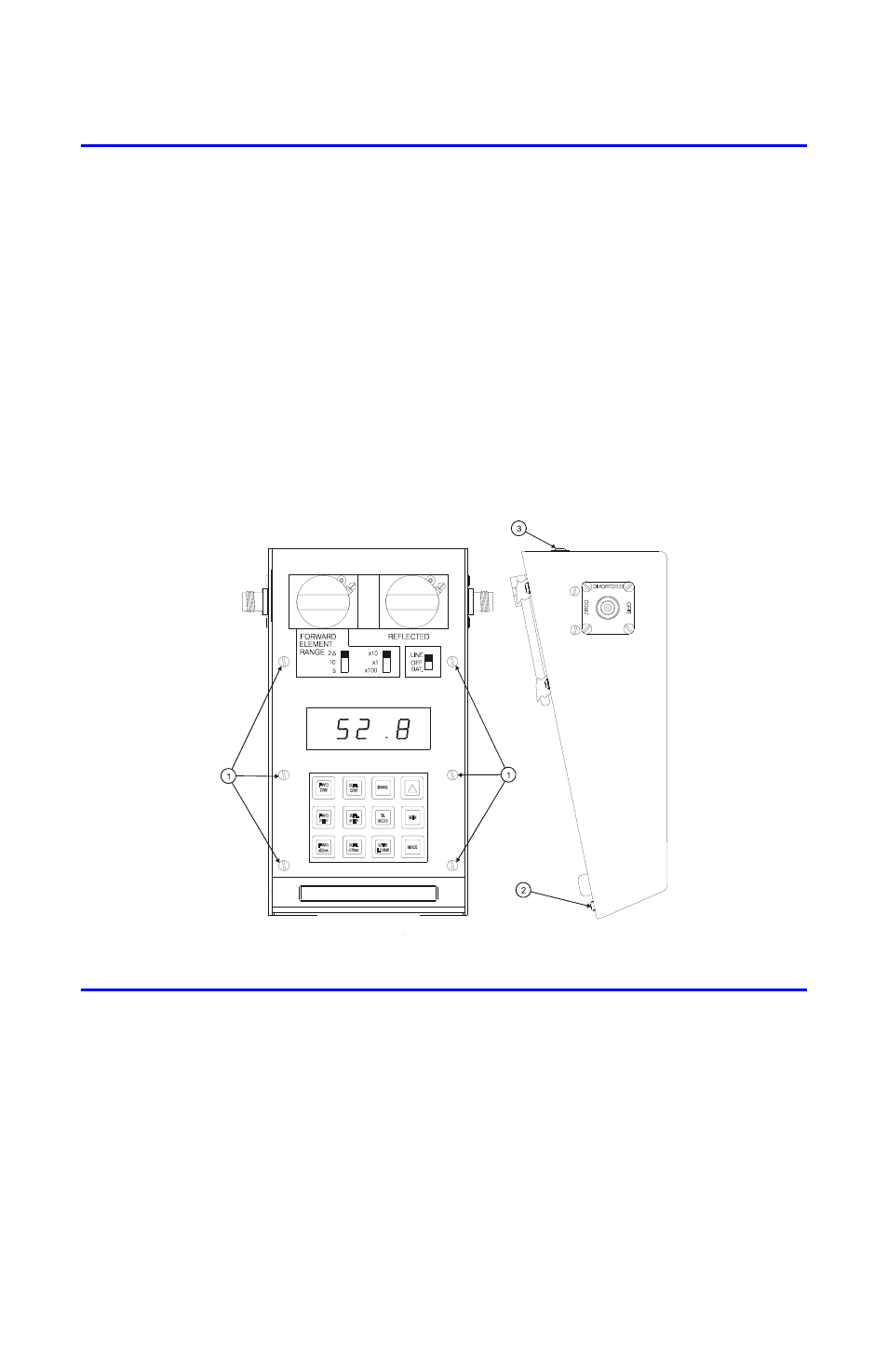
Front Panel Removal
1.
Disconnect AC power from the instrument.
2.
Remove the six screws that secure the front panel to the Main PCB supports
(Figure 18 on page 23, item 1).
3.
Remove the two screws and lock washers that secure the front panel at the bot-
tom of the housing (item 2).
4.
Remove the two screws and lock washers that secure the front panel at the
back of the housing (item 3).
5.
Lift the front panel from the housing.
Note: Be careful to clear the line section blocks.
6.
Remove pads from the three toggle switches.
Figure 18 Removing Front Panel
Main Printed Circuit (PC) Board Removal
1.
Remove the front panel. Refer to "Front Panel Removal" on page 23.
2.
Disconnect cable assembly at header (J4) (Figure 19 on page 24, item 1).
3.
Remove the six screws and washers that secure the circuit board supports
to the housing (item 2).
4.
Lift the Main PC board.
Note: Locate the cable coming from the power supply assembly.
5.
Disconnect the cable assembly at header (J1). (Figure 19 on page 24, item 3).