Initial setup, Figure 15 calibration potentiometer – Bird Technologies 4391A User Manual
Page 31
19
Initial Setup
Note: On a clean flat workspace perform the following setup proce-
dure:
1.
Remove the front panel. Refer to "Front Panel Removal" on page 23.
2.
Insert a DC feed-in adapter into the FWD element of the socket.
3.
Insert a metal dust plug (supplied with the instrument) into the RFL element
socket.
4.
Connect a BNC to BNC cable assembly from the output of calibrator/source
to the DC feed-in adapter.
5.
Set the RF Power Analyst range switches to the 10 and x100 positions.
6.
Connect AC power and place the LINE/OFF/BATT switch to the LINE setting.
7.
Switch on the Calibrator/Source.
8.
Allow it to warm up for at least one hour.
9.
Set the Calibrator/Source to output 30 ±0.05 microamps.
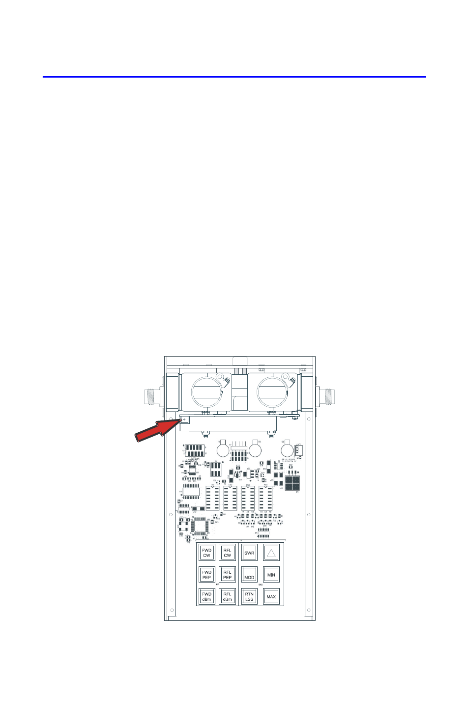
10. Adjust potentiometer, R25 (Figure 15 on page 19), until the RF Power Ana-
lyst Displays 1000 ±5.
Figure 15 Calibration Potentiometer
- SK-4000-TC-Manual (56 pages)
- SK-4000-TC-Datasheet (2 pages)
- SH-36S-Manual (206 pages)
- SH-36S-Datasheet (4 pages)
- SH-36S-PC-Manual (130 pages)
- SH-36S-PC-Datasheet (2 pages)
- SH-36S-PC-Quick Start (2 pages)
- SH-36S-RM-Datasheet (2 pages)
- SA-3600XT-Manual (112 pages)
- SA-3600XT-Datasheet (2 pages)
- AT-500-Manual (73 pages)
- AT-500-Datasheet (2 pages)
- AT-800-Manual (74 pages)
- 89-83F-02-03-Manual (2 pages)
- 89-83F-02-03-Datasheet (1 page)
- 8251 Series-Datasheet (1 page)
- 8251 Series-Manual (30 pages)
- DA10 VHF Series-Datasheet (2 pages)
- DA10 VHF Series-Manual (47 pages)
- 8865SC13-Datasheet (2 pages)
- 8865SC13-Manual (28 pages)
- 8890-300SC13-Manual (28 pages)
- 8921SC13-Manual (28 pages)
- 8931-115SC13-Manual (34 pages)
- BDS-Datasheet (2 pages)
- BDS-Manual (98 pages)
- SCC7 Series-Datasheet (2 pages)
- SCC7 Series-Manual (45 pages)
- MSCC7 Series-Datasheet (2 pages)
- MSCC7 Series-Manual (35 pages)
- SCC8 Series-Datasheet (2 pages)
- SCC8 Series-Manual (47 pages)
- 4020 Series-Datasheet (1 page)
- 4020 Series-Manual (4 pages)
- 4027A Series-Datasheet (2 pages)
- 4027A Series-Manual (6 pages)
- 4027F Series-Datasheet (2 pages)
- 4027F Series-Manual (6 pages)
- 4028 Series-Datasheet (2 pages)
- 4028 Series-Manual (6 pages)
- 7022-Datasheet (4 pages)
- 7022-Manual (27 pages)
- ACM Series-Datasheet (2 pages)
- ACM Series-Manual (40 pages)
- BPME Series-Datasheet (4 pages)