Rf connector – Bird Technologies 8327-300 User Manual
Page 22
s Ohmmeter with an accuracy of ±1% at 50 Ohms.
s Temperature of the load between 20°C to 25°C (68°F to 77°F)
Accurate measurement of the dc resistance between the inner and outer conductors
of the RF input connector will provide a good check of the condition of the load
resistor. Checking the dc resistance is simply used to measure a change in the
condition of the resistor over time. The tracking of the dc resistance must start
before
the resistor is first put into service. Perform the following steps and record the value
for future comparison. Check and record the resistance of the load periodically
according to use.
WARNING
Never attempt to disconnect the equipment from the transmission line while RF power is
being applied. Leaking RF energy is a potential health hazard.
1. Turn off RF power and interlock circuitry before any electrical dis-
connection’s are made.
2. Disconnect the RF coaxial line.
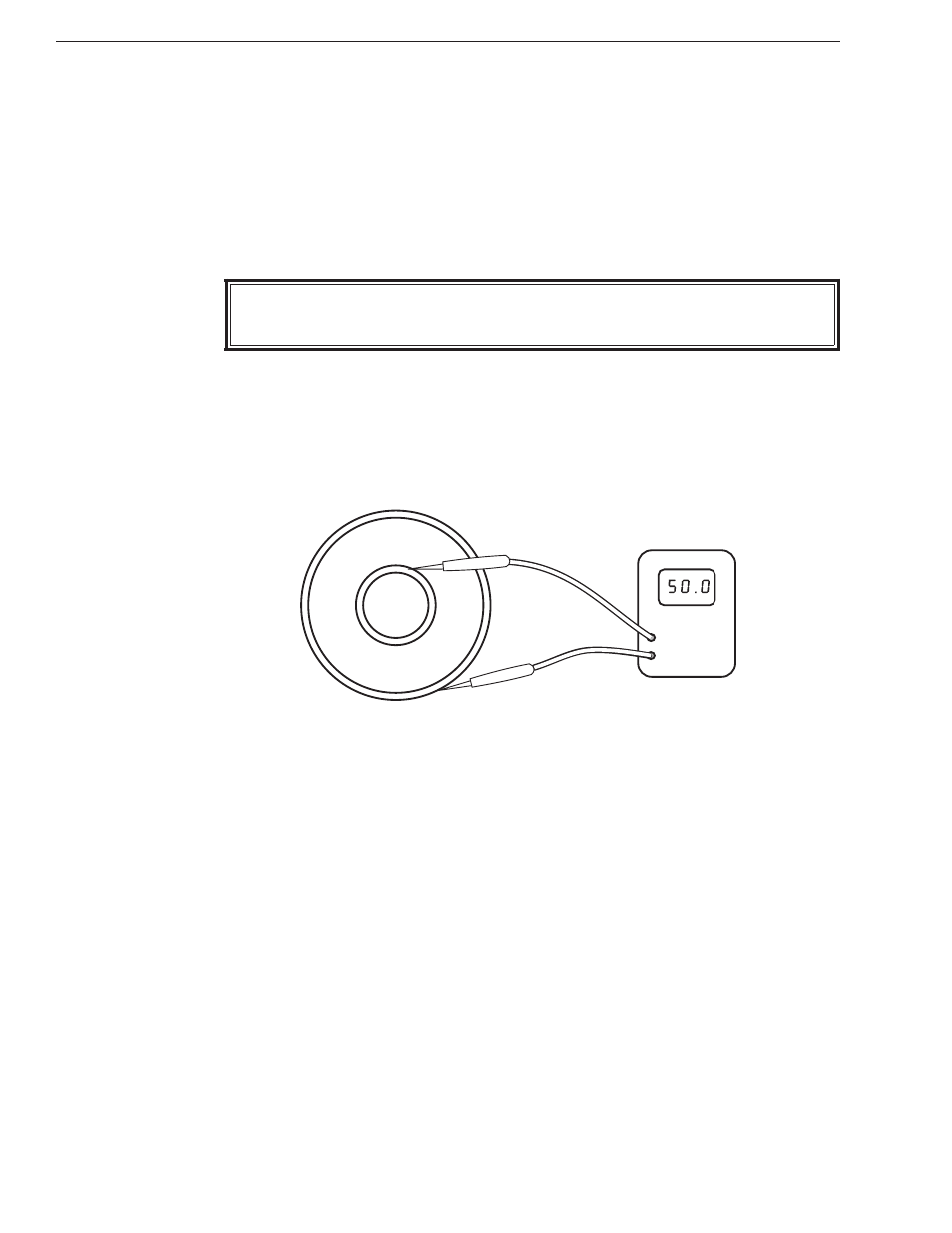
3. Connect the multimeter test leads across the center and outer con-
ductor of the load resistor. Refer to figure 5.
4. Record the value of the resistance
before the load is put into service.
Compare subsequent values with the latest reading. If the values
vary more than 2 ohms, this could be an indication of a failing
resistive element.
+
Note: It is recommended that this resistance check be performed each time the
load is to be used.
RF Connector
Tool required:
s Screwdriver
The following paragraphs outline the component removal and replacement procedure.
The connector is a “Quick-Change” design which permits easy interchange with the
use of only a screwdriver. This process does not interfere with the essential coaxial
continuity of the attenuator RF input, out put, or the coolant oil seals. For replace-
ment, proceed as follows:
1. Remove and retain the four screws from the corners of the RF
connector.
Figure 5
Meter Lead
Placement
Bird Model 8327-300 Attenuator
12