Bird Technologies 8327-300 User Manual
Page 17
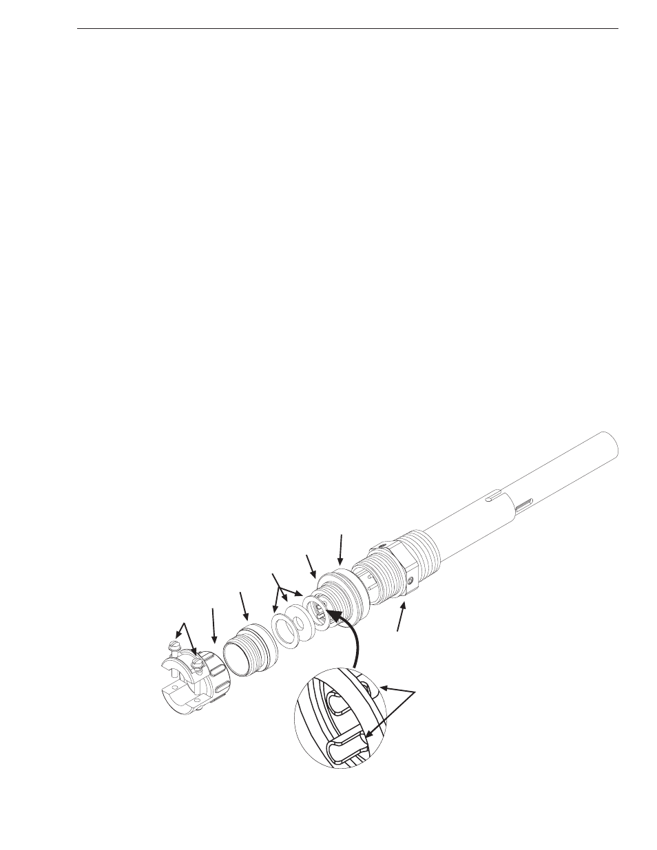
While following the instructions below for connecting the thermoswitch, refer to figure
4.
1. Unscrew the larger knurled ring-nut (A) at the lower end of the
coupling jack assembly. Pull it off from the thermoswitch jack (B).
Unscrew the small knurled cover fitting (C) from the base plug (D)
of the connector to release the base.
2. Thread the interlock wires through the clamp (E) with the washers
(F) inside and with its threaded fitting in place.
3. Service the interlock wire with short tips, use spaghetti sleeves over
the wire ends if needed.
4. Securely solder the interlock leads to the lugs (G) of the connector
base.
+
Note: Be sure that the larger captive clamping nut (A) is in place over the base
plug (D) with the knurled end outward towards face.
5. Screw on the cover ring (C) first, then fasten the cable clamp (E) in
place, and tighten the two yoke screws (H) on the cable. Push the
plug back onto the thermoswitch, and tighten the captive knurled
connecting ring.
Do not attempt to operate the equipment without the
interlock attached.
A
B
C
D
E
F
G
H
Figure 4
Thermoswitch
Assembly
Installation
7