Repair, Front panel, Figure 8 cal cart wiring schematic – Bird Technologies MSCC7 Series-Manual User Manual
Page 26: Cord reel, Power sensor, D 12, Front panel cord reel power sensor
Bird Multi-Sensor Cal Cart System
12
Repair
Front Panel
To access the power sensor or the AC connections, it will be necessary to
remove the front panel of the Cal Cart.
1. Remove both screws on the front panel, between the RF connector and the
handle.
2. Pull on the handle set into the base of the front panel to remove it.
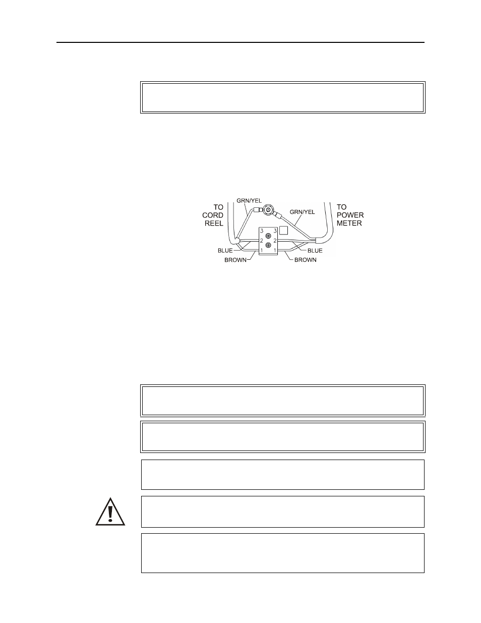
Figure 8 Cal Cart Wiring Schematic
Cord Reel
1. Disconnect the cord reel from the terminal strip.
2. Unscrew the AC connector.
3. Unscrew and remove the cord reel.
4. Screw the replacement cord reel into place.
5. Thread the AC connector through the grommet.
6. Replace the ring terminal on the green/yellow wire.
7. Connect the wires on the other end to the terminal strip (See Figure 8).
Power Sensor
WARNING
To avoid personal injury, disconnect the power cord from the AC line before
performing any maintenance, including fuse replacement.
WARNING
To avoid personal injury, disconnect the power cord from the AC line before
performing any maintenance, including fuse replacement.
WARNING
Never attempt to connect or disconnect RF equipment from the transmission line
while RF power is being applied. Leaking RF energy is a potential health hazard.
CAUTION
The Bird 4421 must be powered off when connecting or disconnecting the
power sensor from the power meter.
CAUTION
Changing the sensor’s connectors will invalidate calibration data, and may
reduce the maximum power rating of the unit.
CAUTION
Due to the complexity of the Bird Power Sensor, field repairs beyond general
maintenance should not be attempted. Removal or disturbance of the power
sensor cover can result in cancellation of lifetime warranty.