Maintenance, Safety considerations, Power supply load units – Rockwell Automation T3512 ICS Regent Power Supply Modules User Manual
Page 6
I/O Power Supply Modules (T3510, 11, and 12)
6
Industrial Control Services
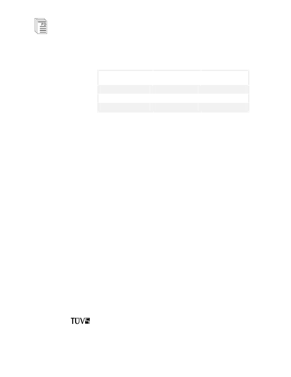
Use Table 1 to verify voltage compatibility for your I/O power
supply chassis and I/O power supply modules.
Table 1. Matching Input Power Voltages.
Input Power Voltage
I/O Power Supply
Chassis
I/O Power Supply
Module
110 VAC
T3500
T3510
220/240 VAC
T3501
T3511
24 VDC
T3502
T3512
Power Supply Load Units
Power supply unit loading is based on the number of I/O
modules in the chassis and the load imposed by each I/O
module. Load units for each I/O module are shown in that
module’s product description and specification sheet under the
heading “Safetybus Power.” I/O power supply load units are
shown on page 7, as “Available Load Units.”
Calculating the number of load units in your system will help
you determine the number of I/O power supplies your system
will need. For economic power distribution, and to avoid
overloading individual power supply units, power supply
loading should be calculated when configuring systems.
Maintenance
No periodic maintenance or calibration is required for I/O
power supply modules. There are no user replaceable parts
inside these modules.
When an I/O power supply module fails, it can be hot-replaced
without disrupting system operations. Main power wiring and
I/O power cables (connected to the chassis) are not disturbed
during module replacement.
Safety Considerations
The T3510 (110 VAC) and T3512 (24 VDC) I/O power supply
modules are TÜV certified for Risk Class 5 safety critical
applications. Model T3511 (220 VAC) is excluded as it does