5 liquid-cooling connections, Side view top view front view – Rockwell Automation Liqui-Flo Trane Addendum User Manual
Page 22
3-6
Trane Liqui-Flo Addendum
3.5
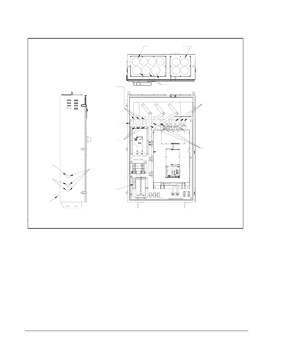
Liquid-Cooling Connections
External coolant lines connect to the cabinet through two bulkhead fittings. The
bulkhead fittings are located on the rear panel of the cabinet as shown in figure 3.5.
Use the following steps to connect the coolant lines to the cabinet:
Step 1. Be sure the threads of the bulkhead fittings and the CenTraVac chiller’s
tubing connectors are free of dirt, burrs, and excessive nicks.
Step 2. Apply liquid sealer to the pipe thread end of the chiller’s tubing connectors.
Screw the connectors into the cabinet’s bulkhead fittings until they are
finger-tight. See figure 3.6.
Figure 3.4 – Cabinet Wire Routing Locations (12-Pulse Rectifier)
3-Phase AC
Volt Input to
Signal
Control
Wiring
3-Phase
AC Volts
Output to
Motor
Line Side
T3
T5
T1
T6
T2
T4
of Circuit
to Primary of
of Circuit Breaker
from Load Side
Volt Output
3-Phase AC
Delta-Wye
from Secondary of
Liqui-Flo Drive
3-Phase AC Volt
Input to C-Frame
Side View
Top View
Front View
Bulkhead
Coolant
2 Pl.
(0.875")
22.23 mm
(1.125")
28.58 mm
Cabinet Here
Wiring Enters
Signal Control
Ground Stud
Connections
(Left Side Wall)
Recommended, 3 Pl.
127.0 mm (5.0")
111.1 mm (4.38")
Recommended, 8 Pl.
Transformer
Delta-Wye Transformer
Fittings
Breaker
30A
10A
2A
15A
15A
(6 Places)