Rockwell Automation 440R MSR312 Configurable Monitoring Safety Relay w/DeviceNet Communications User Manual
Page 6
Configurable Monitoring Safety Relay with DeviceNet™ Communications
Chapter 1: Overview of the MSR312P DeviceNet Base Module
6
MSR312-UM001B-EN-P
Chapter 1: Overview of the MSR312P DeviceNet Base Module
Description
The MSR312P offers DeviceNet connection for applications in which network communication is desired. All of the functionality
of the DeviceNet interface is contained within the enclosure. The base unit requires two 24V DC power sources. One is
connected to A1/A2 terminals to power the safety circuitry including all connected modules. The second is the DeviceNet power.
It’s recommended that they do not share the same source.
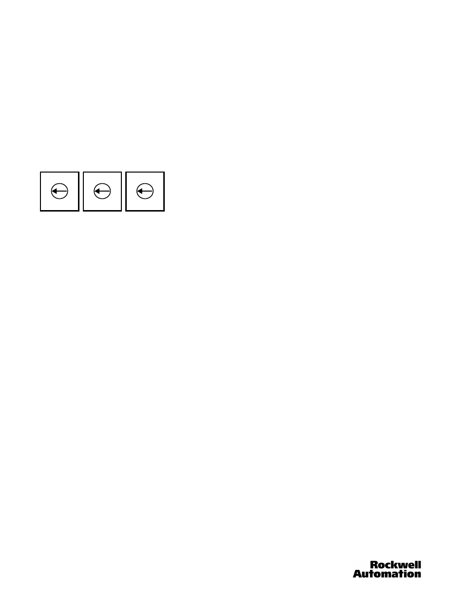
Rotary Switches
The MSR312P has three 10-position rotary switches for setting: DeviceNet baud rate and DeviceNet node address The
switches are located on the side of the enclosure. The switch settings and functions are shown below.
S1 S2 S3
MSB
LSB
Node Address Baud Rate
MSB = Most Significant Byte
LSB = Least Significant Byte
Node Address Configuration
Rotary switches S1 and S2 are used to set the node address (0…63) of the MSR312P. The factory default is 63 on the switches.
If the node address is between 64…99, the MAC ID will be software settable. Rotate switches S1 and S2 to the desired address.
Data Rate Configuration
Rotary switch S3 sets the data rate at which the MSR312P communicates with the network. The factory default setting is
0…125 kb.
DeviceNet Connection
The MSR312P DeviceNet communications receives its power and communications through the DeviceNet Cable. A separate
power supply is required to power the MSR312P for its safety functions. This separate power supply must be connected to
terminals A1 and A2 of the MSR312P.
•
CANH – White Wire
•
CANL – Blue Wire
•
V+ – Red Wire
•
V- – Black Wire
•
SHD – Shield
12
345
678
90
12
345
678
90
12
345
678
90