Rockwell Automation 440R MSR312 Configurable Monitoring Safety Relay w/DeviceNet Communications User Manual
Page 15
Configurable Monitoring Safety Relay with DeviceNet™ Communications
Chapter 2: Device Parameters
MSR312-UM001B-EN-P
15
Parameter 95—Configuration Consistency Value (read only)
This parameter indicates the unique value of an installation. The value lies in the range of 0…65535
Parameter 96—Serial Number (read only)
This parameter provides a unique identifier when multiples of the same product are being used on a network. The allowable
values lie in the range from 0…4294967295.
Parameter 97—Runtime (read only)
The number of hours the device has been operating. This value is updated every 2 hours and resets after each power-up.
Parameter 98—Power-up Count (read only)
The total number of times the device has been power cycled.
Parameter 99—DeviceNet Voltage (read only)
This parameter gives the network voltage seen by the device. Voltages outside of the specified range of 11…25V DC may cause
the device to report inaccurate information and should not be relied upon.
Parameter 100—Number of Input Modules (read only)
This parameter indicates the number of MSR320P or MSR329P Input Modules currently attached to the system. A mismatch
between this value and the number of Input Modules stored in nonvolatile memory will cause a fault.
Parameter 101—Number of Input Modules in Nonvolatile Memory (EEPROM) (read only)
This parameter indicates the number of MSR320P or MSR329P Input Modules stored in nonvolatile memory. A mismatch
between this value and the number of actual Input Modules will cause a fault.
Parameter 102—MSR Processor Version Number (read only)
This parameter indicates the version number of the microprocessors in the MSR312P module.
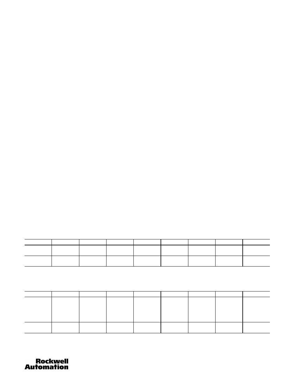
Parameter 103—105: Input Assembly (POLL, COS, and Strobed)
These three parameters allow the user to read and set preselected data assemblies. Select Parameter 103 for Polling, 104 for
COS, and 105 for Strobing. The choices for each parameter are the same, and are made by a pull down menu. To change the
selection, remove the MSR312P from the Scanlist, then apply and download the change. The selections are:
1.
Group State, Group Status, and System Status: Group State with Status
This consists of 2 bytes in (Parameters 30…32, 36…38, and 81)
2.
System and Muting Lamp Diagnostic Byte.
This consist of 2 bytes in (Parameters 80 and 82)
Byte
Bit 7
Bit 6
Bit 5
Bit 4
Bit 3
Bit 2
Bit 1
Bit 0
In 0
Reserved
Reserved
Group 3
Active
Group 3
Ready
Group 2
Active
Group 2
Ready
Group 1
Active
Group 1
Ready
In 1
Reserved
Reserved
Reserved
Reserved
Reserved
Group 3
Interrupted
Group 2
Interrupted
Group 1
Interrupted
Byte
Bit 7
Bit 6
Bit 5
Bit 4
Bit 3
Bit 2
Bit 1
Bit 0
In 0
Current config
unlike stored
config
Any hardware
failure
Config
changed
during
operation
Terminal
connector is
missing
Internal Fault
Cross Loop
Actual #
Modules not
equal to
memory
value
Invalid code
switch setting
In 1
Reserved
Reserved
Reserved
Reserved
Reserve Lamp
2 Faulty
Muting Lamp
2 Faulty
Reserve Lamp
1 Faulty
Muting Lamp
1 Faulty