Additional resources, Install the protective covers – Rockwell Automation 20B PowerFlex 700 Dynamic Brake Kit User Manual
Page 7
Rockwell Automation Publication PFLEX-IN030A-EN-P - July 2014
7
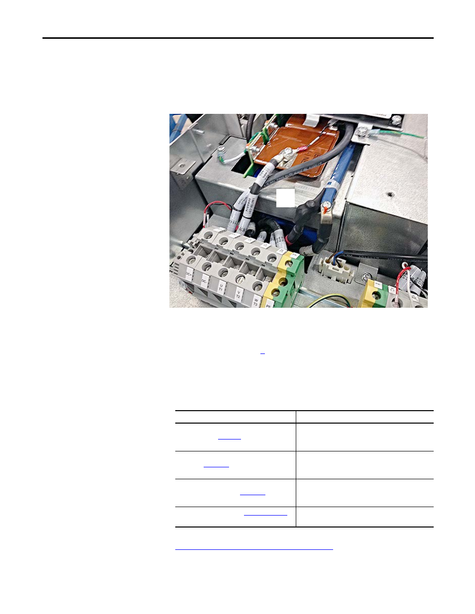
PowerFlex 700/700S Frame 5 Drives 600/690V Brake Bus Bar Insulator Installation
8. If necessary, reinstall the MOV on the drive chassis by using the existing
hardware. Tightening torque is 3.16 N•m (28 lb•in).
9. Shrink the tube over the cable and bus bar connection by using a heat gun.
Note: The tube does not need to conform fully to the bus bar and/or
cable, but must not be able to move after shrinking.
Install the Protective Covers
Install the protective covers in the reverse order of removal. See. Remove the
Protective Covers on page
. Tightening torque for the clear-plastic protective
cover is 1.69 N•m (15 lb•in). Tightening torque for the drive cover is 1.69 N•m
(15 lb•in).
Additional Resources
These documents contain additional information on related products from
Rockwell Automation.
You can view or download publications at
To order paper copies of
technical documentation, contact your local Allen-Bradley distributor or
Rockwell Automation sales representative.
9
Resource
Description
PowerFlex 700 Installation Instructions - Frames
0…6, publicatio
Provides the information that is required to install and
perform a Basic Start-Up of the PowerFlex 700 (Series A or B)
AC drive.
PowerFlex 700 Standard Control User Manual,
publication
Provides the information that is required to install, start-up,
and troubleshoot the PowerFlex 700 Adjustable Frequency AC
Drive.
PowerFlex 700 AC Drives Vector Control User Manual
(v4.001 and up), publication
Provides the information that is required to program and
troubleshoot the PowerFlex 700 Adjustable Frequency AC
Drive with Vector Control.
Product Certifications website,
Provides declarations of conformity, certificates, and other
certification details.