What this kit contains, Recommended tools, Installation – Rockwell Automation 20B PowerFlex 700 Dynamic Brake Kit User Manual
Page 2: Remove power from the drive
2
Rockwell Automation Publication PFLEX-IN030A-EN-P - July 2014
PowerFlex 700/700S Frame 5 Drives 600/690V Brake Bus Bar Insulator Installation
What This Kit Contains
One piece of Tyco Electronics heat shrink tube (1.5…2.0 in.), part number
RNF-3/4-1-BK-STK. Note: If this part is lost or damaged, it is acceptable to use
another 1.5…2.0 in. piece of UL Listed equivalent heat shrink tube in its place.
Recommended Tools
The following list of tools is provided for your reference to disassemble and
reassemble the drive and components. You may need more tools than are listed
based on your situation.
• Volt ohm meter
• Torque wrench (metered in N•m or lb•in) with a Torx head bit
• Needle-nose pliers
• Heat gun
Installation
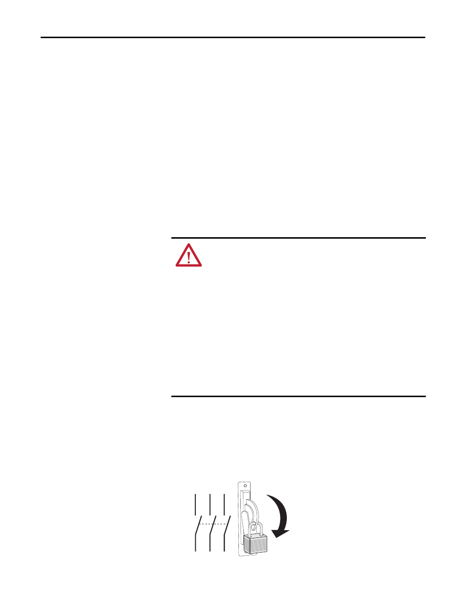
Remove Power from the Drive
1. Turn off and lock out input power. Wait 5 minutes.
2. Verify that there is no voltage at the drive’s input power terminals.
3. Check the DC bus voltage at the power terminals by measuring between
the +DC and –DC terminals, between the +DC terminal and the chassis,
and between the –DC terminal and the chassis. The voltage must be zero
for all three measurements.
ATTENTION: To avoid an electric shock hazard, ensure that all power has been
removed before proceeding. In addition, before servicing, verify that the
voltage on the bus capacitors has discharged. Check the DC bus voltage at the
Power Terminals by measuring between the +DC and -DC terminals, between
the +DC terminal and the chassis, and between the -DC terminal and the
chassis. The voltage must be zero for all three measurements.
Remove power before making or breaking cable connections. When you remove or
insert a cable connector with power applied, an electrical arc can occur. An
electrical arc can cause personal injury or property damage by:
• sending an erroneous signal to your system’s field devices, causing unintended
machine motion.
• causing an explosion in a hazardous environment.
Electrical arcing causes excessive wear to contacts on the module and its mating
connector. Worn contacts can create electrical resistance.
L1
L2
L3
O
I