Connect wiring to the remote termination panel, Connect the cables to the remote termination panel – Rockwell Automation 1897-NOV High Speed Analog Installation Instructions User Manual
Page 5
Remote
Termination
Panel (RTP)
channel 2
19621
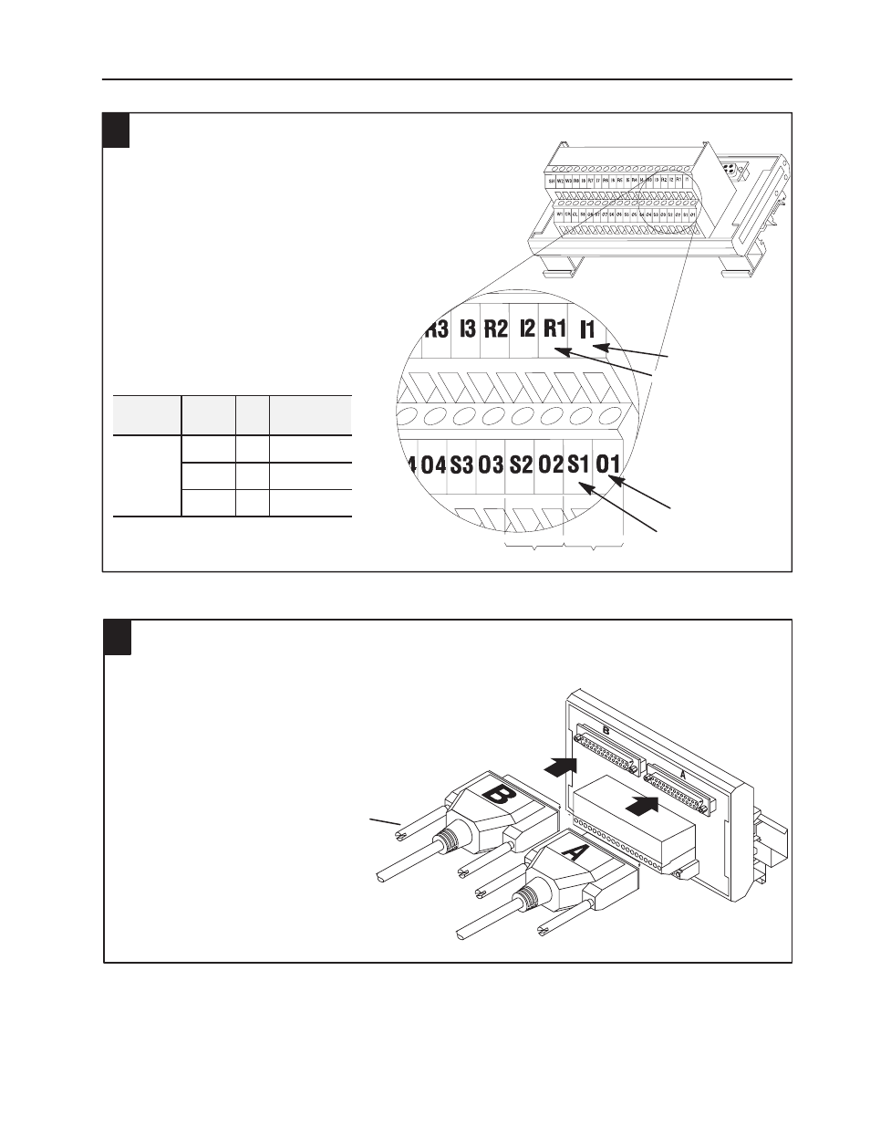
Each channel has four connections: R, I, O, and S.
Field wiring to the RTP is the same for all RTP variations.
Channel 1 uses R1, I1, O1, and S1; channel 2 uses R2, I2,
O2, and S2; and so on for the remaining channels.
I = input
O = output
Field Wiring
S = shield
channel 1
R = return
4
1. Strip 3/8 inch (9.25 mm) of insulation from
the 22-12 AWG wire.
2. Insert the wire into the open connector slot.
3. Tighten the screw to clamp the wire.
Connect Wiring to the Remote
Termination Panel
The 1897-NOV module is cable-connected to a 1771-RTP4
remote termination panel using cat. no. 1771-NC6 (6 ft) or
-NC15 (15 ft) cables. This RTP has straight-through wiring. The
remote termination panel mounts on standard DIN 1 or DIN 3
mounting rails.
Fast Isolated Analog Output Module
5
Publication CIG-5.1 – April 1998
Output
Type
Connect
To
+
O1
Output
Voltage
-
R1
Return
Shield
S1
Shield
RTP End of
1771-NC cable
11024-I
RTP4
DIN R
Channel 1 Connections
R1 = Return 1
I1 = Input 1
O1 = Output 1
S1 = Shield 1
Note: Terminals W1, W2
and W3 are spares.
Do not use terminals CR
and CL.
Example:
Connect the Cables to the
Remote Termination Panel
5
1. Insert the RTP end of the cable into the connector
on the the RTP.
2. Alternately tighten the retaining screws into
the connector on the RTP until secure.
Screw