I/o status leds, Outputs and gate outputs, Table 14 default i/o status indicators – Rockwell Automation T8444 Trusted TMR Pulse Generator and Monitoring Module User Manual
Page 29: Trusted, Module t8444
Trusted
TM
Module T8444
Issue 09 Apr 10
PD-T8444
29
4.3. I/O Status LEDs
There are 40 channel status indicators on the module front panel, one for each field input/output.
These indicators are controlled by the FPU. The FPU receives data from each of the module slices.
The FPU performs a 2-oo-3 vote on each data bit from the slices and sets the indicators accordingly.
The input/output status indicator mode is dependent upon the numerical state of the channel. Each
state can be defined to have a particular indicator mode: off, green, red, flashing green, or flashing red.
The configurable indicator modes allow users to customise the status indications to suit individual
application requirements. Without customisation, the default indicator modes are suitable for damper
control installations as described below. Each channel is provided with a Bicolour Led. The channel
LED’s illuminate as follows.
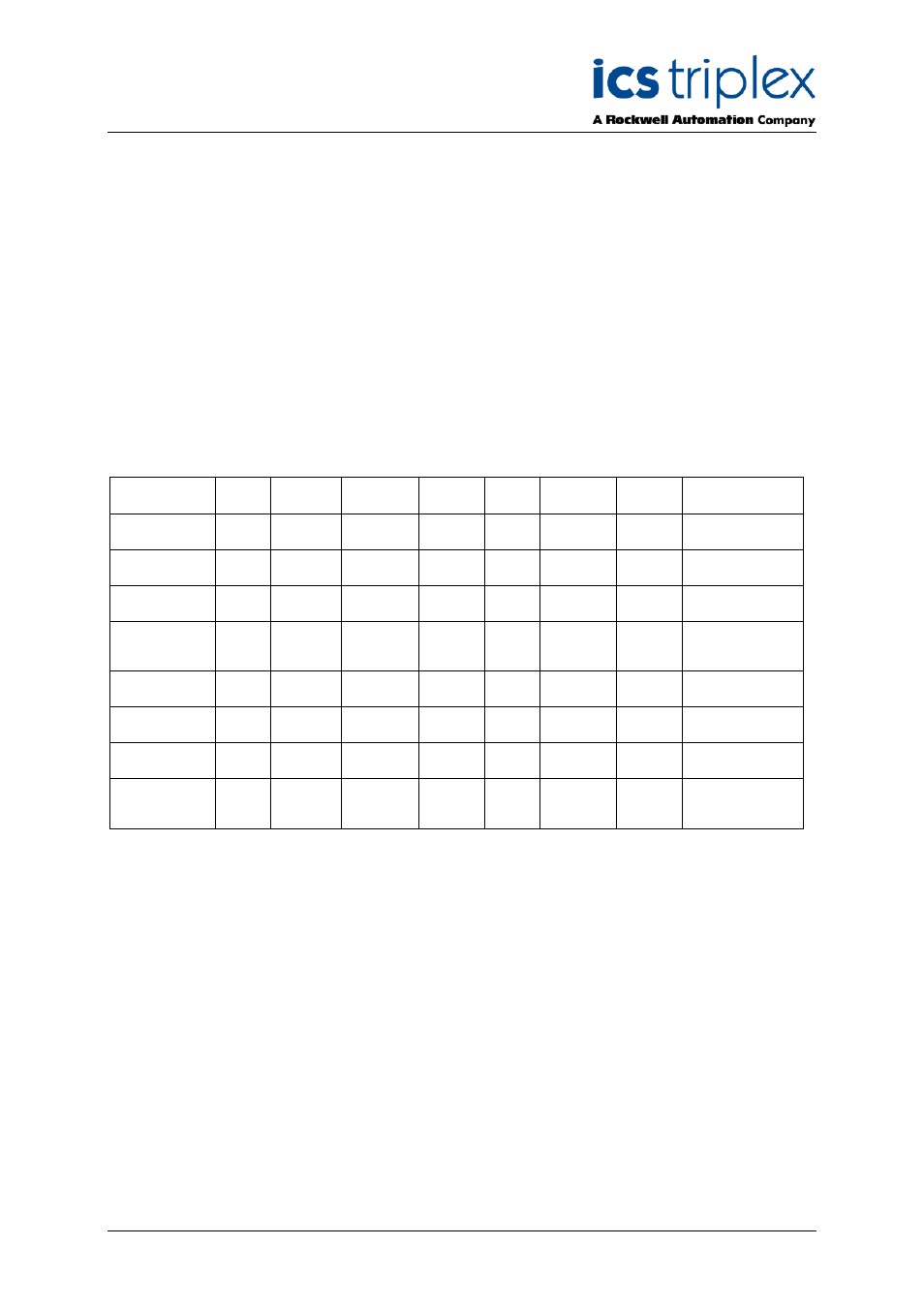
4.3.1. Outputs and Gate Outputs
Function
Off
Green
Steady
Green
Flash
Red
Steady
Red
Flash
Amber
Steady
Amber
Flash
Note
Output off no
faults
Yes
Not
allowed
Not
allowed
Slice LED’s Green
Output Off with
Module Fault
Yes
Not
allowed
Not
allowed
Slice LED’s Red
Output Off with
field Fault
Not
allowed
Not
allowed
Yes
Slice LED’s Green
Output off with
Module and
Field Fault
Not
allowed
Not
allowed
Yes
Slice LED’s Red
Output on No
Faults
Not
allowed
Not
allowed
Yes
Slice LED’s Green
Output On with
Module Fault
Not
allowed
Not
allowed
Yes
Slice LED’s Red
Output On with
Field Fault
Not
allowed
Not
allowed
Yes
Slice LED’s Green
Output on with
Module and
field Fault
Not
allowed
Not
allowed
Yes
Slice LED’s Red
Table 14 Default I/O Status Indicators