Technical specifications, Technische daten, Spécifications techniques – Rockwell Automation FERROGARD GD2 Magnetically Actuated Interlock Switch User Manual
Page 3
Conforming to standards
EN1088, EN292, EN60204-1
Safety contact arrangement
Types 1AC, 2AC , for AC circuits only
1N/C special safety reed - 250VAC 2A max
(fuse externally 1.6A quick blow)
Types 20AC, 21AC, for AC circuits only
2N/C special safety reed - 250VAC 2A max
(fuse externally 1.6A quick blow)
Types 1DC, 2DC, for DC circuits only
1N/C special safety reed - 24V DC 1amp max
(fuse externally 800mA quick blow)
Types 20DC, 21DC, for DC circuits only 2N/C special safety reed - 24V DC 1amp max
(fuse externally 800mA quick blow)
Safety contact operating distance
Make 12mm - Break 23mm
Auxiliary contact operating distance
Types 2 & 21
Break 10mm - Make 13mm
Reed contacts
Safety
Auxiliary
Closing time
3.0mS
0.5mS
Drop out time
2.1mS
0.3mS
Bounce time
0.7mS
0.7mS
Shock
50G
100G
Vibration
7-15G’s, 10 to 200Hz
Initial contact resistance
15m
Ω
1Om
Ω
Initial capacitance, terminals
0.65 pF
0.2pF
Initial insulation res. terminals 1 x 10
6
OHMS
1 x 10
6
OHMS
Min. initial b/down voltage
600VAC RMS
600VAC RMS
Auxiliary contact arrangement
Types 2, 21
1N/O
300VDC, 250VAC (RMS) 0.5A INC.
INRUSH. 15VA/10W. for AC/DC circuits
Case material
Stainless Steel BS3146 Pt 2 Anc 4BFC
Protection
IP68
Operating temperature
–25
°
C to 125
°
C
Fixing
M4 tamper resistant
Mounting configuration
Any position
Mechanical life
10 x 10
6
Electrical life
1 x 10
6
Colour
Silver
Cleaning
May be high pressure steam cleaned
Cable
Stranded 7 core. Flexible thermoplastic
elastomer sheathed 7/0.5mm
NOTE: The safety contacts of the Guardmaster switches are described as
normally closed (N/C) i.e. with the guard closed, actuator in place and the
machine able to be started.
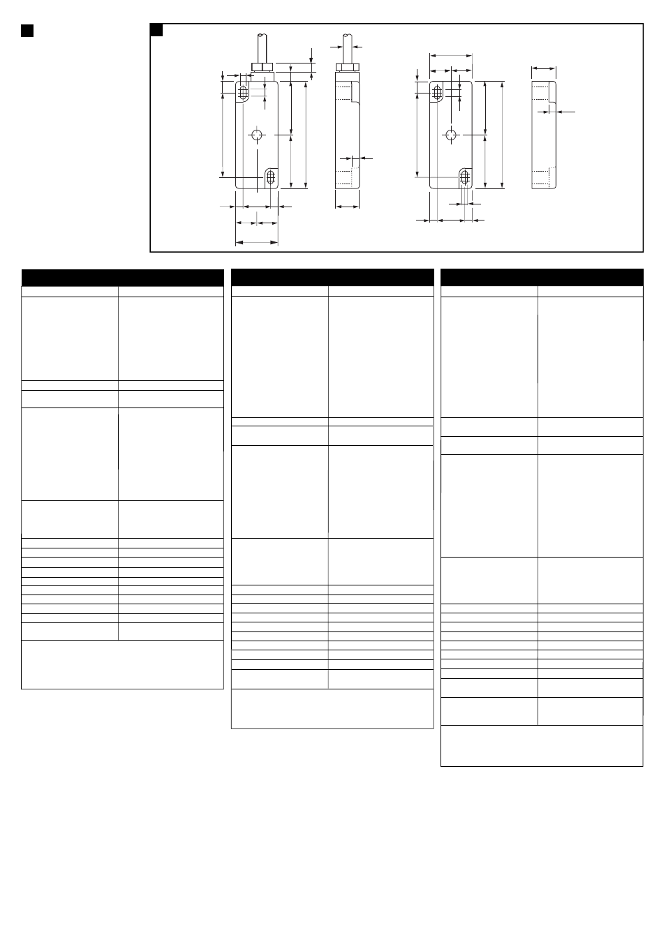
(d)
Technical Specifications
16
11.50
8
7
19.5
7
7
7
4.4
39.25
39.25
78.5
16.75
16.75
16.75
16.75
33.5
62.5
11.5
5
62.5
19.5
33.5
78.50
4.4
8
6
(a)
SWITCH
16
5
(b)
ACTUATOR
9
39.25
39.25
8
7
Normative Auslegung entsprechend: EN 1088, EN 292, EN 60204-1
Schutzkontaktanordnung
Typen 1AC, 2AC - nur für AC-Schaltkreise 1 Spezial-Reed-Schutzkontakt -
250 V AC, 2 A max (Ruhekontakt).
(Mit externer Flinksicherung 1,6 A sichern)
Typen 20 AC, 21 AC - nur für
2 Spezial-Reed-Schutzkontakte -
AC-Schaltkreise
250 V AC, 2 A max (Ruhekontakte).
(Mit externer Flinksicherung 1,6 A sichern)
Typen 1 DC, 2DC - nur für DC-Schaltkreise 1 Spezial-Reed-Schutzkontakt -
24 V DC, 1 A max (Ruhekontakt).
(Mit externer Flinksicherung 800 mA sichern)
Typen 20 DC, 21 DC - nur für
2 Spezial-Reed-Schutzkontakte -
DC-Schaltkreise
24 V DC, 1 A max (Ruhekontakt).
(Mit externer Flinksicherung 800 mA sichern).
Schutzkontakt-Funktionsdistanz
EIN = 12 mm, AUS = 23 mm
Hilfskontakt-Funktionsdistanz
Typen 2 und 21
AUS = 10 mm, EIN = 13 mm
Reed-Kontakte
Schutzkontakt Hilfskontakt
Schließzeit
3,0 ms 0,5 ms
Abfallverzögerung
2,1 ms 0,3 ms
Prellzeit
0,7 ms 0,7 ms
Stoß
50 G 100 G
Vibration
7 - 15 G, 10 - 200 Hz
Anfängl. Kontaktwiderstand
15 m
Ω
10 m
Ω
Anfängl. Kapazität, Klemmen
0,65 pF 0,2 pF
Anfängl. Isolierwiderstand, Klemmen 1 x 10
Ω
1 x 10
Ω
Min. anfängl. Durchschlagsspannung 600 V AC eff. 600 V AC eff.
Hilfskontakt-Auslegung
Typen 2, 21
1 Schließkontakt
300 V DC, 250 V AC (eff.), 0,5 A INKL.
EINSCHALTSTROM, 15 VA/10 W für
AC/DC-Schaltkreise
Gehäusematerial
Rostfreier Stahl BS 3146 Teil 2 Anc 4 BFC
Schutzklasse
IP 68
Betriebstemperatur
-25
°
C bis 125
°
C
Montage
M4, eingriffsicher
Montageanordnung
In beliebiger Position
Mechanische Lebendauer
10 x 10
Elektrische Lebensdauer
1 x 10
Farbgebung
Silber
Reinigung
Kann mit Hochdruckdampf erfolgen
Kabel
Verseilt, 7-adrig. Abschirmung
Thermoplastik-Elastomer 7/0,5 mm
ANMERKUNG: Die Schutzkontakte der Guardmaster-Schalter werden als
Ruhekontakte beschrieben, d.h. bei geschlossener Schutztür, Betätiger in
Position, und startbereiter Maschine.
Technische Daten
Conforme aux normes suivantes EN 1088, EN 292, EN 60204-1
Disposition des contacts de sécurité
Types 1 c. alternatif, 2 c. alternatif 1 commutateur à lames spécial N/F -
pour circuits c. alternatif seulement 250 V c. alternatif 2A maximal
(fusible externe : 1,6A instantané)
Types 20 c. alternatif, 21 c. alternatif 2 commutateurs à lames spécial N/F -
pour circuits c. alternatif seulement 250 V c. alternatif 2A maximal
(fusible externe : 1,6A instantané)
Types 1 c. continu, 2 c. continu
1 commutateur à lames spécial N/F -
pour circuits c. continu seulement Voyant 24 V c. continu 2A maximal
(fusible externe : 800mA instantané)
Types 20 c. continu, 21 c. continu 2 commutateurs à lames spécial N/F -
pour circuits c. continu seulement Voyant 24 V c. continu 2A maximal
(fusible externe : 800mA instantané)
Distance de service du contact de Contact : 12 mm
sécurité
Coupure : 23 mm
Distance de service du contact auxiliaire
Types 2 et 21
Contact : 10 mm Coupure : 13 mm
Contacts des lames
Sécurité
Auxiliaire
Temps de fermeture
3,0 ms
0,5 ms
Temps de désexcitation
2,1 ms
0,3 ms
Temps de saut
0,7 ms
0,7 ms
Décharge
50 G
100 G
Vibration
7 - 15 G, 10 - 200 Hz
Résistance de contact initiale
15 m
Ω
10 m
Ω
Capacité initiale, bornes
0,65 pF
0,2 pF
Isolation initiale, bornes rés.
1 x 10
Ω
1 x 10
Ω
Tension minimum initiale de
600V c. alternatif efficace
coupure
Disposition des contacts auxiliaires
types 2, 21
1 N/O
300V c. continu, 250V c. alternatif
(efficace) 0,5A inc. d’entrée,
15VA/10W pour circuits DC
Matériau du boîtier
Inox BS3146 Pt 1 Anc 4BFC
Protection
IP68
Température de service
-25
°
C à 125
°
C
Fixation
M4 infraudable
Configuration de montage
Toutes positions
Durée de vie mécanique
10 x 10
Durée de vie électrique
1 x 10
Couleur
Argent
Nettoyage
Peut être nettoyé à la vapeur haute
pression
Câble
Toronné 7 conducteurs, gaine
élastomère thermoplastique souple
7/0,5 mm
REMARQUE : les contacts de sécurité des interrupteurs Guardmaster sont
décrits comme étant normalement fermés (N/F) ; autrement dit, avec porte
de protection fermée, émetteur en place et machine en mesure de démarrer.
Spécifications Techniques
9
(a)
SCHALTER / Récepteur
(b)
BETÄTIGER / Emetteur
6
6
6
6
6
6
6
6