Connections to the 700s control frame – Rockwell Automation 20D PowerFlex 700H/S Frame 11 Replacement Power Structure User Manual
Page 9
PowerFlex® 700S and 700H Frame 11 Replacement Power Structures
9
Step 5: Connecting the
Power Structure to
Components in the Drive
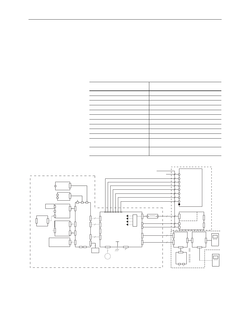
You must connect the power structure to control components on the control
frame. If the drive has DC input, you must also connect the precharge
circuit.
Connections to the 700S Control Frame
When installing a power structure in a PowerFlex 700S drive, you must
make the following connections between the ASIC and Fiber Optic
Interface, Power Supply Voltage Feedback, Common Mode Filter and
Rectifier boards.
Figure 4 Connections for 700S Drives with Phase II Control
Connect this component: termination
point in the Power Structure to …
…this component : termination point on the
Control Frame
ASIC Board: H1 (fiber optic connector)
Fiber Optic Interface Board: J8 (fiber optic connector)
ASIC Board: H2 (fiber optic connector)
Fiber Optic Interface Board: J9 (fiber optic connector)
ASIC Board: H3 (fiber optic connector)
Fiber Optic Interface Board: J10 (fiber optic connector)
ASIC Board: H4 (fiber optic connector)
Fiber Optic Interface Board: J11 (fiber optic connector)
ASIC Board: H5 (fiber optic connector)
Fiber Optic Interface Board: J12 (fiber optic connector)
ASIC Board: H6 (fiber optic connector)
Fiber Optic Interface Board: J14 (fiber optic connector)
ASIC Board: H7 (fiber optic connector)
Fiber Optic Interface Board: J13 (fiber optic connector)
ASIC Board: X10
Insulate and do not connect
ASIC Board: X2
Rectifier Board: X13 (AC input drives only)
Power Supply Voltage Feedback Board: J8
Common Mode Filter Board: J5
Power Supply Voltage Feedback Board: J5
(fiber optic connector)
Fiber Optic Interface Board: J6
Power Supply Voltage Feedback Board: J4
(fiber optic connector)
Fiber Optic Interface Board: J7
HIM
P10
P12
P6
P21
P2
P3
80
P1
Comm
Input
P1
Feedback
Inputs
P2
P3
P11
J1
2
9
20
10
120
34
Compact I/O
P1
34
J2
-U
-V
-W
DC-
DC+
J8
+24V
J4 Tx
J5 Rx
X3
J3
J2
J1
X2
X1
HIM
DOOR
EXTERNAL DPI
X4
2
PWR
STS
PORT
MOD
NET A
NET B
DPI Assembly
EXAMPLE:
20-HIM-A3
20-VB00601
2
Main
Control
Board
Feedback
Option
Board
Logix
Expansion
Board
NetLinx
Daughtercard
M6
J17
J18
J15
External
24V DC
1 = 24V
3 = Common
(75W min)
J5
J6 Tx
J7 Rx
J4
2
2
+24 V Iso
+12 V
-12 V
+5V
Pan Fan
Control
J16
Fiber Optic
Interface
Board
80W
Power
Supply
Power Supply
Voltage
Feedback
DPI
Interface
Board
DPI
Comm
Option
DPI
Bezel
Fiber Optic Cables
J8 J9 J10 J11 J12 J14 J13
M
Fiber
8
9
9
ASIC Board
H1 (Gate Enable)
H2 (U Gate)
H3 (V Gate)
H4 (W Gate)
H5 (ADconv)
H6 (Vbus Tx)
H7 (Vbus Rx)
X2
DriveLogix
Battery
J3
P1
40
J2
P2
30
J1
P5
P4
TB2
TB1
P3
RS232
P2
CompactFlash
Memory
P13
P3
16
Second Encoder
or
Safe Off Option Board
P3
P1
SynchLink
Option Board
RX
TX
P2
Embedded
EtherNet I/P
Option Board
RJ45
Connector
P1
P7
P9
8
Inside Power Structure
Make and verify these connections
700S Control Assembly (Phase II)
J5
J1
2
Common Mode Filter Board
To X13 Connector for Rectifier Board (AC Input Drives Only)
X10