Step 1: configuring the new power structure – Rockwell Automation 20D PowerFlex 700H/S Frame 11 Replacement Power Structure User Manual
Page 2
2
PowerFlex® 700S and 700H Frame 11 Replacement Power Structures
Step 1: Configuring the
New Power Structure
Before configuring the power structure you must remove the protective
covers from the drive. Refer to publication PFLEX-IN006
…
, Installation
Instructions - PowerFlex 700S and 700H High Power Drives, for assistance
in removing these covers.
Configuring a DC Input Drive
Power structures are shipped from the factory pre-configured for DC input
operation.
Connecting an AC Input Drive
Power structures are shipped from the factory pre-configured for DC input
operation. When installing a replacement power structure on a drive with
AC input, you must remove the X2 plug from it’s protective sleeve and plug
the cable into the ASIC and Rectifier board(s).
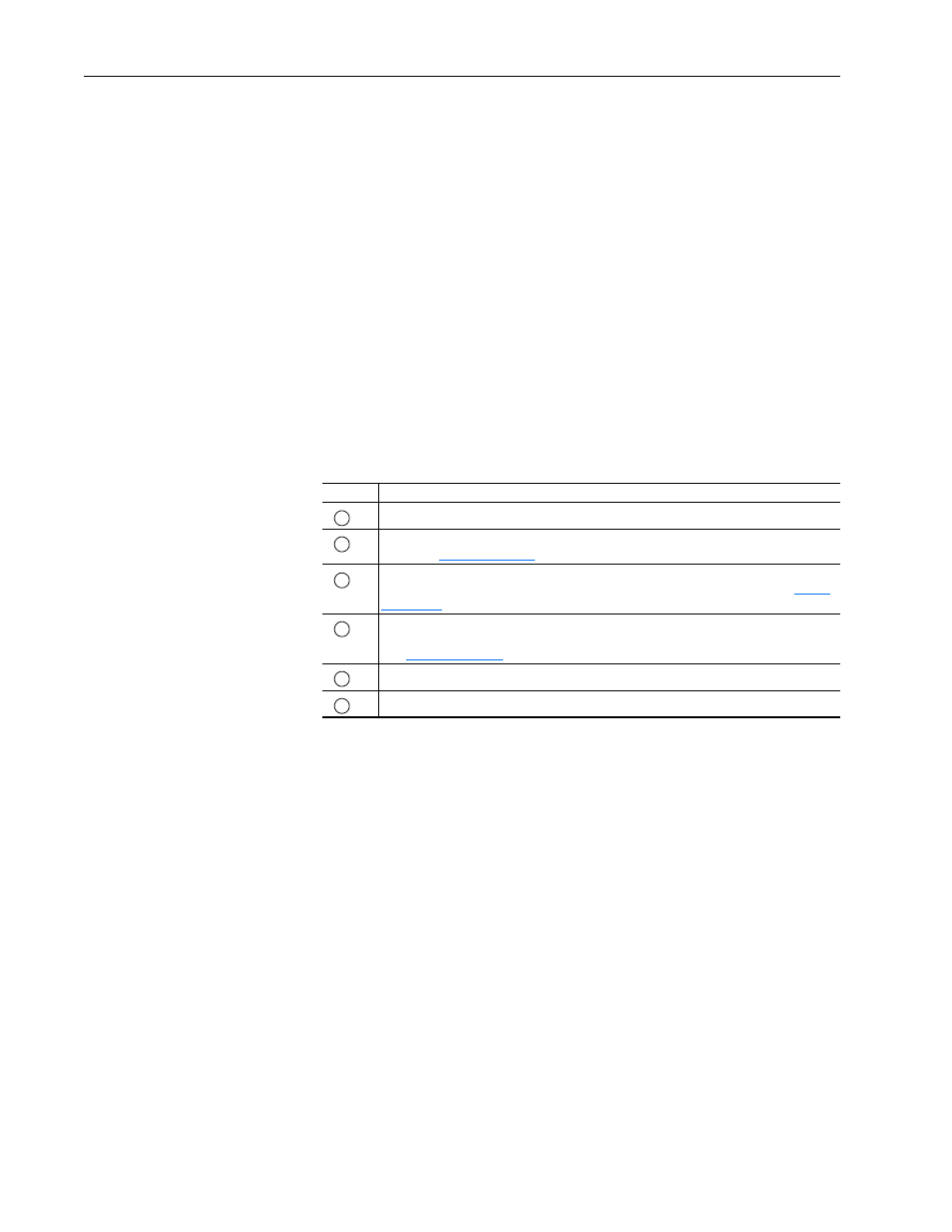
Task
Description
Remove the cover from the ASIC board assembly.
Disconnect the ASIC fan from the assembly by unplugging the cable from X1 on the ASIC
board (see
for location).
Remove the cover from the connector on the loose cable (bundled with the flat gate driver
board cables) and connect the cable to the X2 connector on the ASIC board (see
for location).
Connect the other end of the cable connected to X2 on the ASIC board to the X13
connector for the Rectifier board(s) on the V Phase and W Phase (if present) power stack
(see
for location).
Connect the fan cable to the X1 connector on the ASIC board.
Install the cover on the ASIC board assembly.
A
B
C
D
E
F