Rockwell Automation 440R MSR23M Minotaur Safety Relay User Manual
Page 2
Input circuit
Nominal Voltage U
N
:
DC 24 V, AC/DC 24 V
Voltage range
DC
AC/DC
DC:
at 10% residual ripple:
0,9 ... 1,1 U
N
0,95 ... 1,1 U
N
at 48% Rresidual ripple:
0,8 ... 1,1 U
N
0,8 ... 1,1 U
N
AC:
—
0,8 ... 1,1 U
N
Nominal consumption:
DC approx. 2 W
Min. Off-time:
1 s
Control voltage on S11:
approx. DC 23 V at U
N
Cross fault current
between line S11-S12 and
line S21-S22 with active
safety mat or safety edge
start-up:
max. 0,4 A for approx. 2 ms
continuously
DC:
approx. 29 mA at U
N
AC:
approx. 37 mA at U
N
Control current over
S12, S22:
40 mA at U
N
Min. voltage on S12, S22:
DC 21 V when relay activated
Short-circuit protection:
Internal PTC
Overvoltage protection:
Internal VDR
Output
Contacts
Contacts
2 NO, 1 NC contact
Operate delay typ. at U
N
:
Manual start:
40 ms
automatic start:
200 ms
Release delay typ. at U
N
:
Disconnecting the supply:
50 ms
Disconnecting S12, S22:
15 ms
Contact type:
positive guided
Nominal output voltage:
AC 250 V
DC: see limit curve for arc-free operation
Switching of low loads:
≥100 mV
(contact 5 Au)
≥1 mA
Thermal current I
th
:
see current limit curve
on 1 contact path:
max. 8 A
on more then 1 contact path:
max. 7 A per contact path
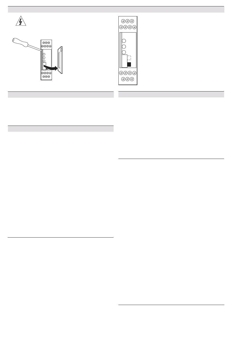
Unit programming
Technical data
Technical data
Switching capacity
to AC 15:
AC 3 A / 230 V
EN 60 947-5-1
for NO contacts
AC 2 A / 230 V
EN 60 947-5-1
for NC contact
Electrical contact life
to AC 15 at 2 A, AC 230 V:
10
5
switching cycles
EN 60 947-5-1
Permissible operating
frequency:
max. 1 200 operating cycles / h
Short circuit strength
max. fuse rating:
6 A gL
EN 60 947-5-1
line circuit breaker:
C 8 A
Mechanical life:
10 x 10
6
switching cycles
General data
Operating mode:
Continuous operation
Temperature range:
- 15 ... + 55 C
Clearance and creepage
distances
Overvoltage category /
contamination level:
4 kV / 2
DIN VDE 0110-1 (04.97)
EMC
Electrostatic discharge:
8 kV (air)
EN 61 000-4-2
HF irradiation:
10 V / m
EN 61 000-4-3
Fast transients:
2 kV
EN 61 000-4-4
Surge voltages
between
wires for power supply:
1 kV
EN 61 000-4-5
between wire and ground:
2 kV
EN 61 000-4-5
Interference suppression:
Limit value class B
EN 55 011
Degree of protection:
Housing:
IP 40
EN 60 529
Terminals: IP 20
EN 60 529
Housing:
Thermoplastic with V0 behaviour
according to UL subject 94
Vibration resistance:
Amplitude 0,35 mm
EN 60 068-2-6
frequency 10 ... 55 Hz
Climate resistance:
15 / 055 / 04
EN 60 068-1
Terminal designation:
EN 50 005
Wire connection:
1 x 4 mm
2
solid or
1 x 2,5 mm
2
stranded ferruled (isolated)
or
2 x 1,5 mm
2
stranded ferruled (isolated)
DIN 46 228-1/-2/-3/-4 or
2 x 2,5 mm
2
stranded ferruled
DIN 46 228-1/-2/-3
Wire fixing:
Box terminal with wire protection,
removable terminal strips
Mounting:
DIN rail
EN 50 022
Weight:
220 g
Dimensions
Width x height x depth:
22,5 x 84 x 118 mm
Notes
Connecting the terminal S21 to the protective ground bridges the internal
short-circuit protection of Line A2 (-). The short-circuit protection of line
A1 (+) remains active. Depending on the operation of the machine, the
switch S1 is set to automatic or manual restart.
Drawing shows setting at the state of delivery
Disconnect unit before setting
Switch S1
Upper position for Auto reset.
Lower position for Manual reset.
Isolate power before removing cover
Screwdriver
S1