Rockwell Automation T8403 Trusted 24V dc Digital input Module - 40 Channel User Manual
Page 21
Trusted
TM
Module T8403
Issue 15 Jun 13
PD-T8403
21
Each input within the housekeeping rack is reported as an integer. In general, the application engineer
will not normally require these inputs. They are provided to aid fault finding and diagnosis and are
often used for reporting and display purposes. If a slice is Fatal, then all reported housekeeping inputs
are set to zero.
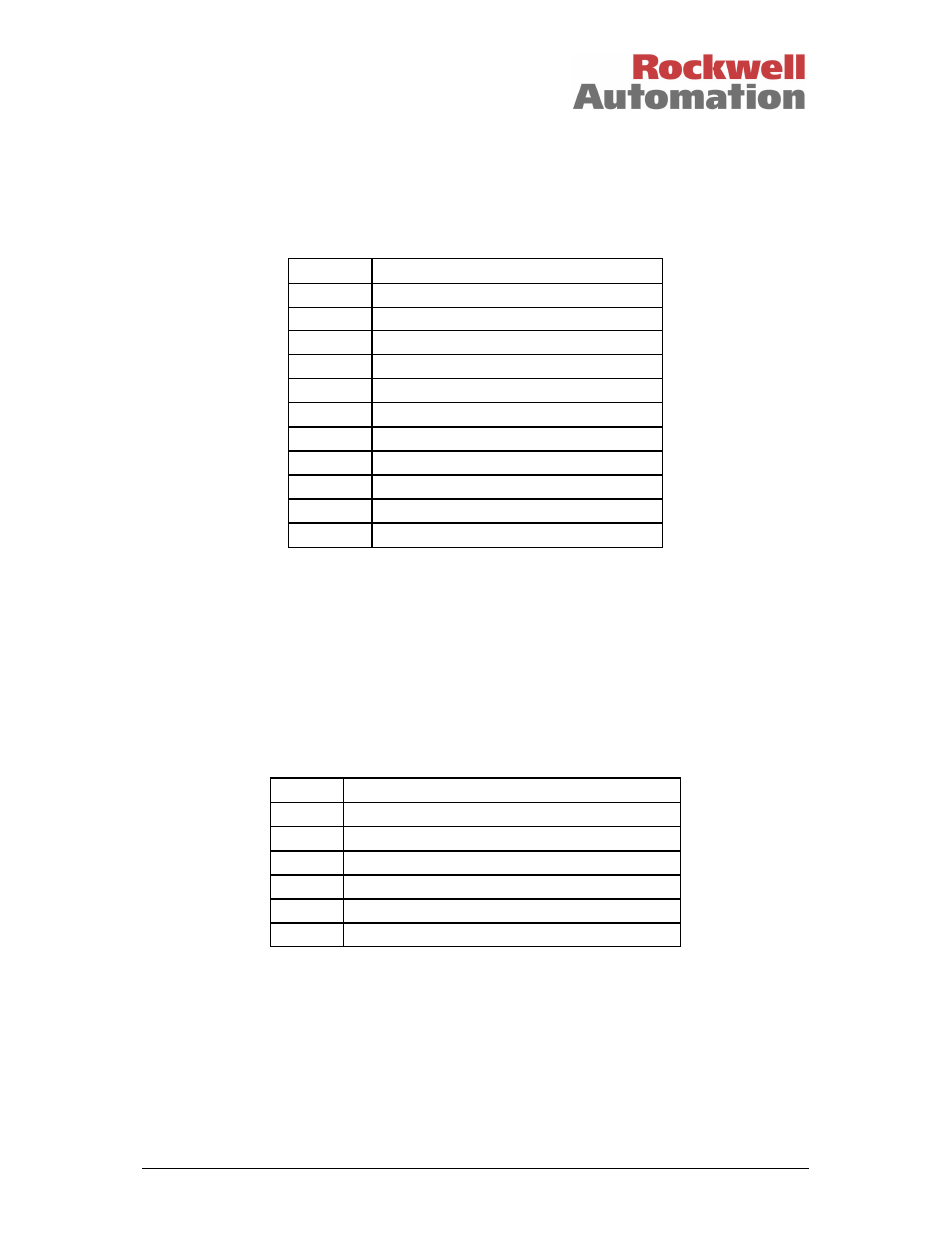
3.2.8. Rack 8: Information
Channel
Description
1
Active module chassis number
2
Active module slot number
3
Active module healthy
4
Active module state
5
Standby module chassis number
6
Standby module slot number
7
Standby module healthy
8
Standby module state
9
Fault Containment Region (FCR) status
10
Primary module is active
11
Active module is simulated
Table 13 Rack 8: INFO Descriptions
The active module chassis and slot numbers indicate the position of the currently active module.
These values will change to match the primary or secondary module position, depending on their active
status, i.e. active/standby changeover will “swap” the values for the active module chassis and slot
number channels with those in the standby module chassis and slot number channels.
The active and standby module healthy channel is returned as an integer. A value of 0 indicates that a
fault has been detected, a value of ‘1’ indicates that the module is healthy.
The active and standby module state is an integer indicating the current operating mode of the
associated module. The value indicates the current internal operating mode of the module.
Value
Module State
5
Shutdown
4
Maintain
3
Active
2
Standby
1
Configuration
0
Unknown, no module present, or module is Fatal
Table 14 Rack 8: INFO bit Descriptions
The FCR status channel reports the fault status of each slice of the active and standby modules. The
value is bit-packed as shown below, the least significant byte is used with the most significant 8-bits set
to zero: