Rockwell Automation 34C473 General Purpose AC Drive DB Kit 5, 7-1/2, 10HP 3-Ph User Manual
Page 3
6. Remove the filter capacitor cover and locate capacĆ
itor terminals 145 (bottom left) and 47 (bottom right)
(Figure 2).
7. Remove the #10 screws from capacitor terminals
145 and 47. Connect leads 145 and 47 of wire harĆ
ness part 705337Ć21R to capacitor terminals 145
and 47, respectively. Reinstall the #10 screws.
8. ReĆinstall the filter capacitor cover.
9. Locate the four preĆdrilled holes in the back of the
NEMA 1 side (right side) of the enclosure. Start the
four supplied #10Ć32 x 3/8'' taptite screws into
these holes but do not tighten fully (Figure 2).
10. Position the keyhole slots of the DB Resistor AsĆ
sembly (part 801450Ć3R) over the taptite screws.
Tighten all four screws.
11. Connect the leads pushed thru the gasket and covĆ
er plate in Step 5. Connect leads 47 and 48 to termiĆ
nals 47 and 48, respectively, on the DB Resistor AsĆ
sembly (Figure 2).
12. Connect one end of wire harness part 60880863TC
(the single orange and black twisted pair) to the
SNUBBER ON" connections on the regulator moĆ
therboard (Figure 3). Polarity is Important. The
orange lead connects to the plus (+) and the black
lead connects to the minus (-). Let the other end of
the harness rest along the enclosure floor unconĆ
nected until connection later in this procedure.
13. Locate the studs in the lower back of the NEMA 12
side (left side) of the enclosure (Figure 2). With the
PC board on the left, position the Base Driver AsĆ
sembly (part 77596Ć88R) over the studs. Using the
provided keps nuts, install the Base Driver AssemĆ
bly on the studs.
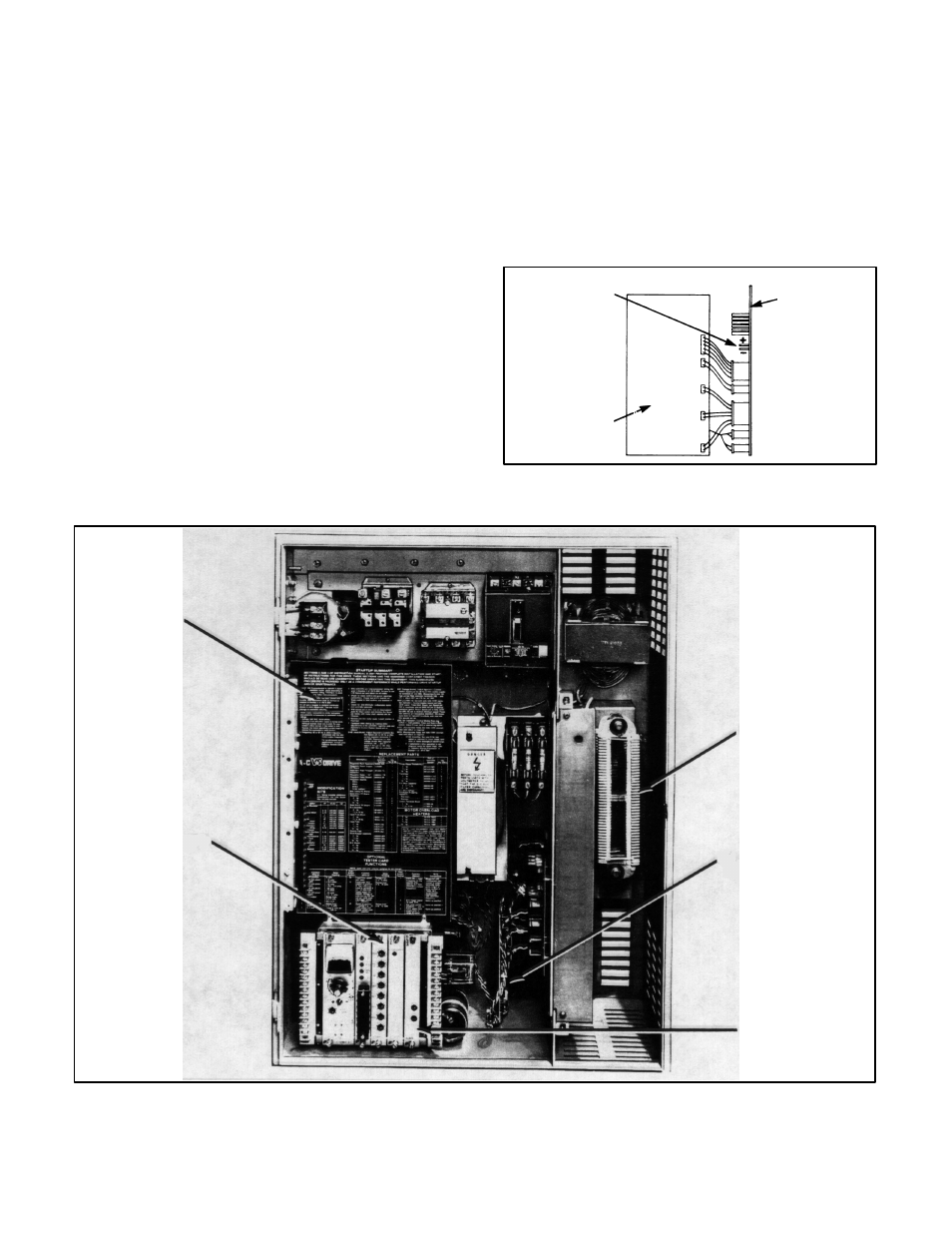
14. Remove the phase module cover (Figure 4).
Connect one end of wire harness part 608808Ć63TD
MOTHERBOARD
SNUBBER ON"
CONNECTION
PSPC BOARD ON
RIGHT SIDE OF
REGULATOR
(+) ORANGE
(-) BLACK
Figure 3. Location of SNUBBER ON" connections
on motherboard.
PHASE
MODULE
COVER
CLSA BOARD
VSAA BOARD
DB RESISTOR
ASSEMBLY
DB BASE DRIVER
ASSEMBLY
Figure 4. Dynamic Braking Kit installed.