Installation – Rockwell Automation 34C473 General Purpose AC Drive DB Kit 5, 7-1/2, 10HP 3-Ph User Manual
Page 2
INSTALLATION
1. Disconnect all power to the AĆC VKS Drive ControlĆ
ler.
DANGER
EQUIPMENT IS AT LINE VOLTAGE WHEN AĆC
POWER IS CONNECTED TO THE AĆC VKS
DRIVE CONTROLLER. ALL UNGROUNDED
CONDUCTORS OF THE AĆC POWER LINE MUST
BE DISCONNECTED FROM THE CONTROLLER
BEFORE IT IS SAFE TO TOUCH ANY INTERNAL
PARTS OF THIS EQUIPMENT. AFTER POWER IS
REMOVED, USE A VOLTMETER TO VERIFY
THAT THE DĆC BUS FILTER CAPACITORS ARE
DISCHARGED BEFORE TOUCHING ANY INĆ
TERNAL PARTS OF THE CONTROLLER.
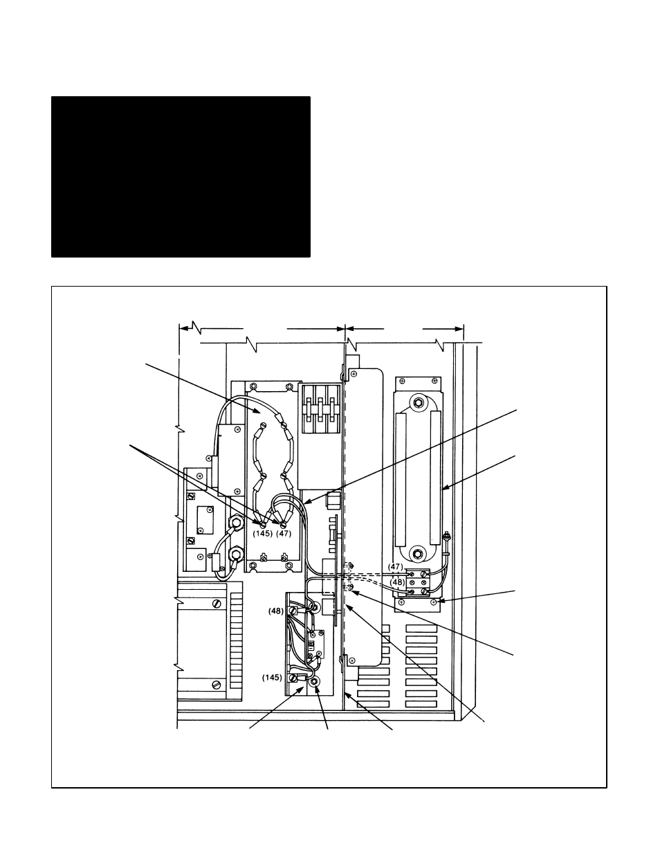
2. Using an 11/32'' wrench, remove the lower cover
plate and gasket from the vertical barrier on the
NEMA 1 side (Figure 2). Discard the gasket.
NOTE: This cover plate and gasket are behind the
Variable Voltage DĆC Supply (SĆ3 Assembly). At the
user's discretion, the Variable Voltage DĆC Supply
can be removed to gain access to this area.
3. Install over the studs on the vertical barrier the two
supplied gaskets (part 417194Ć12C).
4. ReĆinstall the cover plate with hardware removed in
Step 2.
5. Install the nonĆlugged ends of wire harness pair)
705337Ć21R (the only harness not of twisted pair)
thru the gasket and cover plate from the NEMA 12
side (left side) by pushing lead 47 thru the top hole
in the gasket and lead 48 thru the bottom hole.
These two leads will be connected later in this proĆ
cedure.
NEMA 12
NEMA 1
STUD WITH
KEPS NUT
CAPACITOR
COVER REMOVED
CAPACITOR
TERMINALS
WIRE HARNESS
705337Ć21R
DB RESISTOR
ASSEMBLY
TAPTITE
SCREW
COVER PLATE
AND GASKET
VARIABLE
VOLTAGE
DĆC SUPPLY
VERTICAL
BARRIER
DB BASE DRIVER
ASSEMBLY
Figure 2. Initial installation details.