Circuit description, Supply, Dc alarms – Rockwell Automation T823X Trusted Power System User Manual
Page 24: Ac alarms, Table 7 alarm conditions, Trusted, Power system t823x
Trusted
TM
Power System T823X
Issue 9 Dec 08
PD-T823X
24
5.2. Circuit Description
The circuit is split into four functional sections: supply, dc alarms, ac alarms and jumpers.
5.2.1. Supply
The 24V supply is connected to CON3 pins 1 & 6. The supply should be fused close to its source,
using a 500mA F rated fuse. It is nevertheless protected by a non-replaceable fuse on the Power Port.
The 24V is regulated down to 5V with decoupling provided. The 5V+ is used to supply the low voltage
electronics. The 24V is used to supply the relays and is connected through the CON2 to power the
optional Power Controller.
5.2.2. DC Alarms
CON1 is the 25 way D male interface to the Power Shelf. The Power Pack and Power Shelf alarm
outputs are derived from here. There are two dc alarms per Power Pack: DCFAIL (dc output fail) and
OTP (over-temperature protection). The Power Port OR’s together DCFAIL and OTP to give one DC
fail alarm, via CON 3. If either alarm triggers, the corresponding relay de-energises.
Each relay operates a volt free contact. These are closed when healthy (relay energised) and open in
alarm. The contacts share a common return line.
5.2.3. AC Alarms
In a similar manner, each Power Pack generates an AC alarm. When an alarm is triggered, the
corresponding relay de-energises. Each relay operates a volt free contact. These are closed when
healthy (relay energised) and open in alarm. The contacts share a common return line.
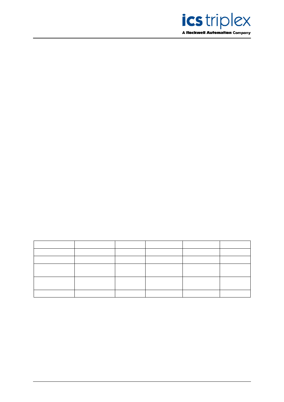
Fault Condition
Output OK LED
OTP Alarm
AC Fail alarm
dc Fail alarm
dc Output
No fault
Green
Low
Closed
Closed
ON
Fan locked rotor
Amber
Low
Closed
Closed
OFF
Secondary over
temperature
Amber
High
Closed
Open
OFF
Primary over
temperature
Off
High
Closed
Open
OFF
AC Feeder Fail
Off
Low
Open
Open
OFF
Table 7 Alarm Conditions