Power port, General description, Figure 11 power port outline drawing – Rockwell Automation T823X Trusted Power System User Manual
Page 23
Trusted
TM
Power System T823X
Issue 9 Dec 08
PD-T823X
23
Con 1
Con 2
Con 3
5. Power Port
5.1. General Description
The Power Port is a supplied accessory and is fitted onto the rear of the Power Shelf. It converts alarm
signals produced by the Power Packs and Power Shelf into volt-free alarm contacts for use by the
system and enables hot replacement of Power Packs. It consists of a pcb fitted with connectors, relays
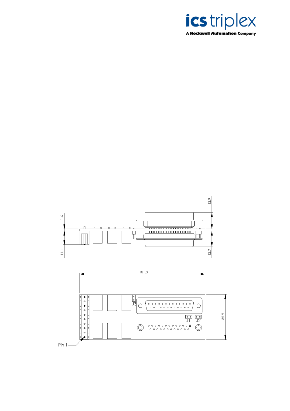
and miscellaneous electronic components. The shape and size of the Power Port is shown in Figure
11.
The alarm contacts are made available on a connector for ease of wiring into the system. The system
provides a supply for the Power Port, which is wired to the same connector. The connector pin-outs are
shown in section 5.3.
The Power Shelf is fitted with a 25 way D female connector to which the Power Port connects. The
Power Port is retained to the Power Shelf by means of the Dsub jack screws. The Power Port is fitted
with a 25 way D female connector to allow the Power Shelf connectivity to be extended to a Power
Controller using a Power Shelf Interconnect ribbon cable.
The Power Controller is powered from the Power Port 24V supply via pin 7, when connecting CON 2
on the Power Port to the Power Controller.
Figure 11 Power Port Outline Drawing