Step 15: apply final torque to all connections, Step 16: install the ac input cables, Step 17: complete the circuit tests – Rockwell Automation 20D PowerFlex 700S and 700H Frame 12 DC Bus Connector Kit User Manual
Page 28
28
PowerFlex® 700S and 700H Frame 12 DC Bus Connector Kit
Step 15: Apply Final Torque
to All Connections
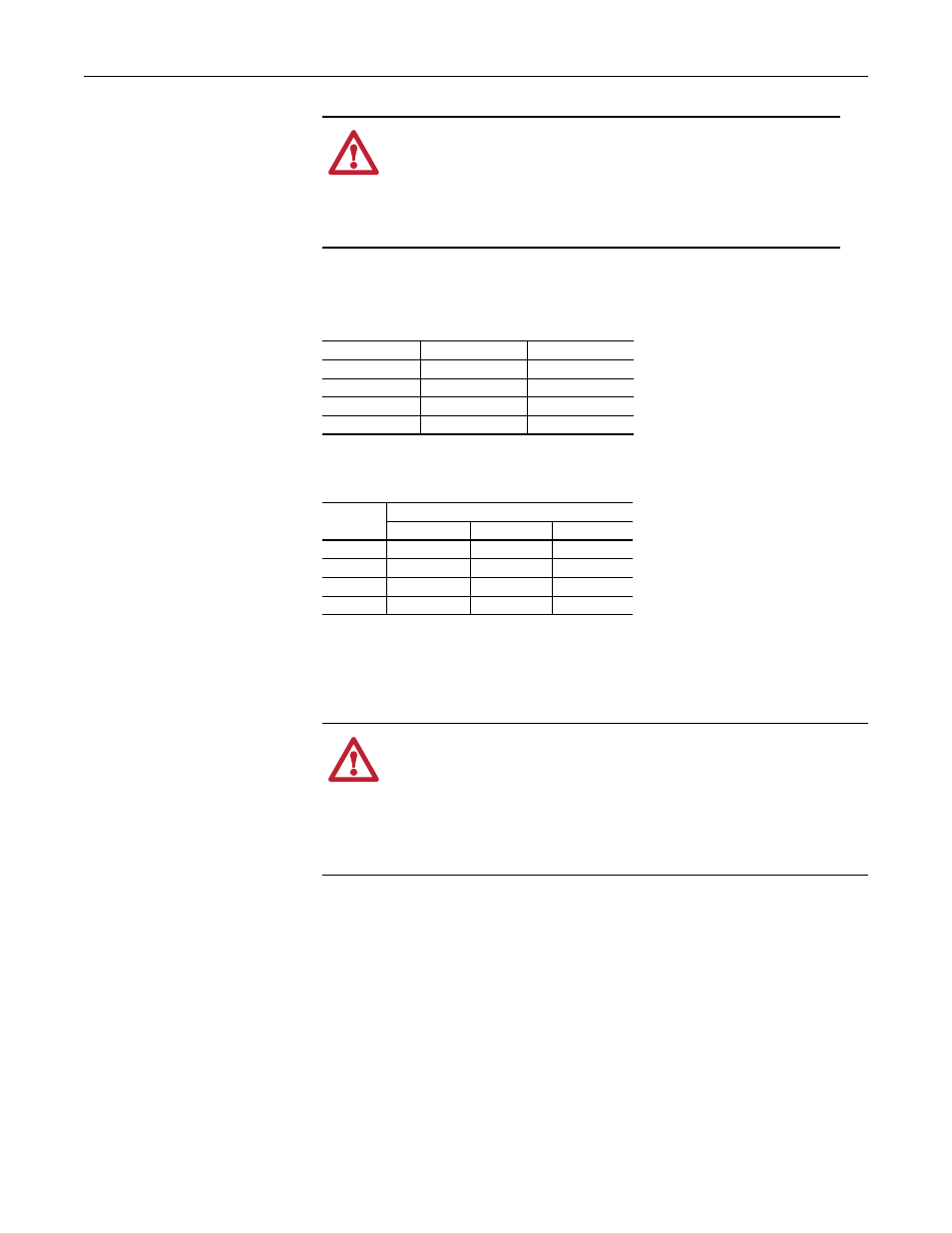
Important: Prior to and after applying the final torque to all connections, you
must verify that the spacing between the bus bars meets minimum
requirements.
•
Apply final torque to all connections. Refer to the table below for torque
specifications.
Step 16: Install the AC Input
Cables
•
If necessary, secure the AC input power cables to terminals 1L1, 1L2 and
1L3, and 2L1, 2L2 and 2L3 with the existing bolts and washers and hex nut.
Step 17: Complete the
Circuit Tests
Forward and Reverse Biased Diode Tests for Major Power Components
A forward biased diode test checks the semiconductor junctions between the
terminals and measures the voltage drop across those junctions. To pass each
test, the meter must display a voltage near 0.5V. If the test finds a short, the
meter will display “.000.” If the test finds an open circuit or reversed polarity,
the meter will display “.0L” (zero load).
A reverse biased diode test should find an open circuit, and the meter should
display “.0L” (zero load).
ATTENTION: National Codes and standards (NEC, VDE, BSI
etc.) and local codes outline provisions for safely installing
electrical equipment. Installation must comply with
specifications regarding wire types, conductor sizes, branch
circuit protection and disconnect devices. Failure to do so may
result in personal injury and/or equipment damage.
Voltage
IEC Clearance
UL508 Clearance
400V
12.70 mm
0.5 in or 12.70 mm
480V
12.70 mm
0.5 in or 12.70 mm
600V
12.70 mm
0.5 in or 12.70 mm
690V
13.80 mm
0.5 in or 12.70 mm
Hardware
Torque
N•m
ft•lb
in•lb
M4
1.36
1.0
12.0
M8
11.3
8.3
100.0
M10
22.6
16.6
200.0
M12
39.5
29.1
350.0
ATTENTION: A hazard of personal injury and/or equipment
damage exists if the AC input power cable insulation becomes
damaged and/or fails. Precautions should be taken to ensure that the
insulation on the AC input power cables is not damaged during bus
bar installation and drive operation. Thoroughly inspect the cable
insulation to verify that no damage has occurred after the bus bar kit
has been installed.