Rtd multiplexer configuration – Rockwell Automation T3432-CA ICS Regent RTD Input Equipment User Manual
Page 11
RTD Input Equipment (T3432)
P D - 6 0 3 7 M a r - 0 6
11
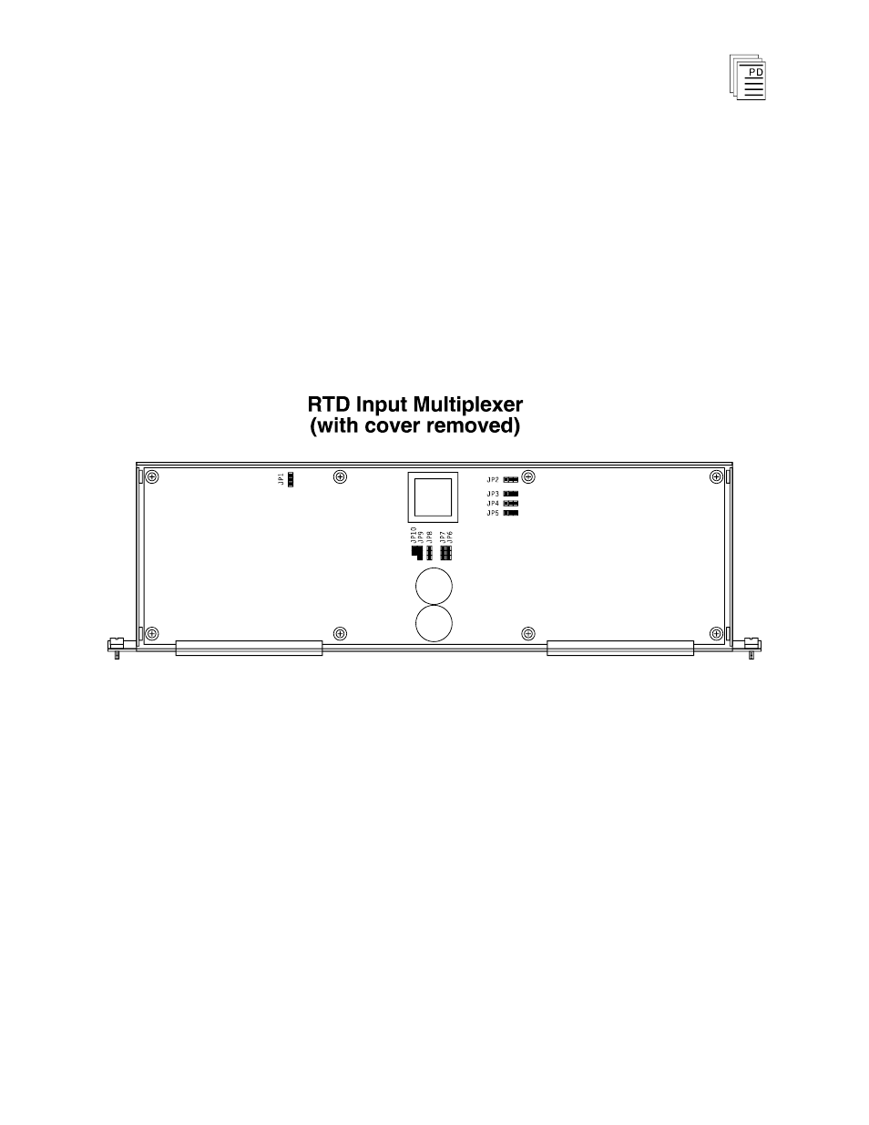
RTD Multiplexer Configuration
The RTD input multiplexer provides jumpers to configure the
RTD types, noise filtering, temperature units, and
temperature resolution. All RTD configuration jumpers are
located on the component side of the Mux as shown in Figure
8. The Mux must be removed from the termination panel and
the Mux housing disassembled to access the RTD
configuration jumpers. To disassemble the multiplexer,
remove two screws from each end of the multiplexer and
remove the loosened cover.
Figure 8. Location of RTD Configuration Jumpers on Mux.
RTD Type Configuration
Each group of eight inputs, 1-8, and 9-16, is individually
configured for RTD type (American or European) and the
number of wire leads (2, 3, or 4-wire).
Selecting American or European Type RTDs
To select American type (a = 0.00392 W/W/° C) or European
type RTDs (a = 0.00385 W/W/° C), position the jumper for
each group as shown in Figure 9. The jumper posts are
labeled “JP5” for group 1 inputs (channels 1 to 8) and “JP6”
for group 2 inputs (channels 9 to 16).